1. المقدمة: فهم الأنابيب الكهربائية الصلبة
في مجال الأنظمة الكهربائية، تلعب المواسير دورًا محوريًا في ضمان السلامة وطول العمر والفعالية.
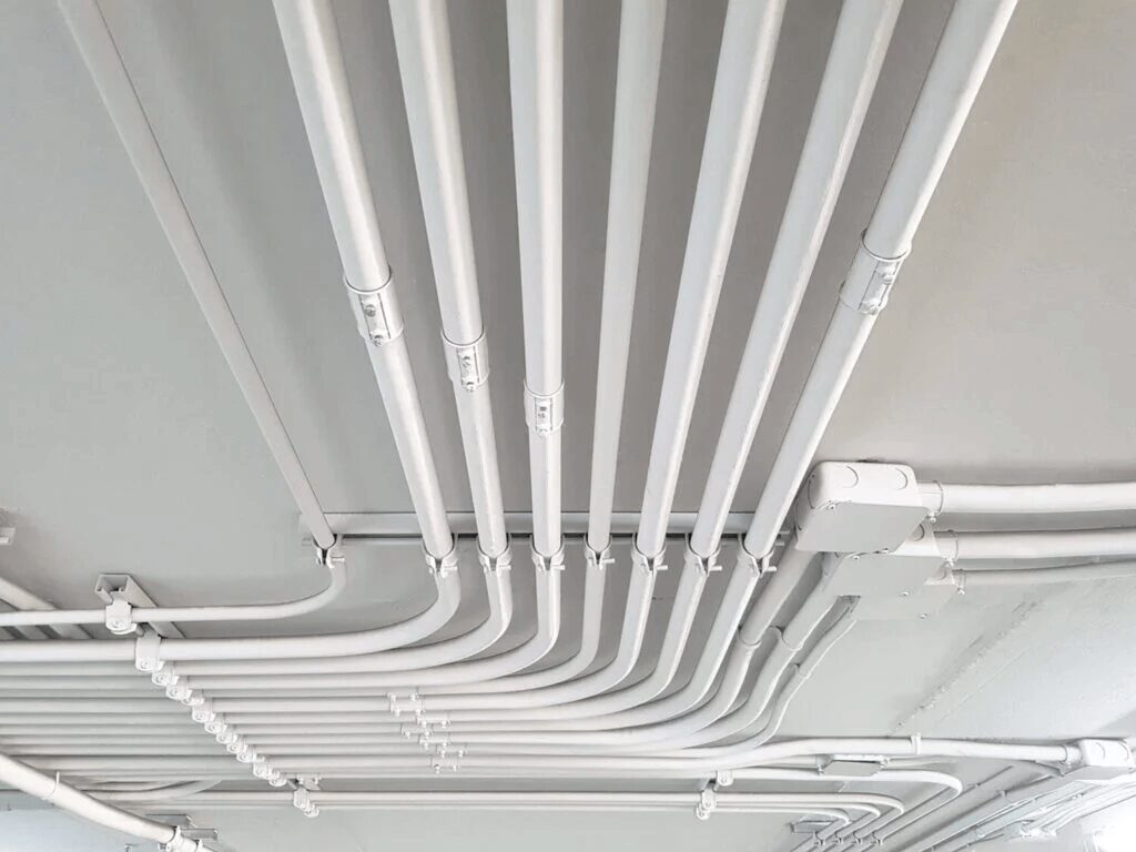
تعمل القنوات الكهربائية كقنوات حماية يتم من خلالها تمرير الأسلاك الكهربائية، مما يحمي الكابلات من التلف المادي والرطوبة والمواد الكيميائية والعوامل البيئية الأخرى.
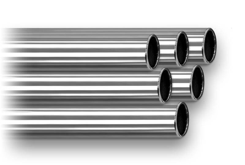
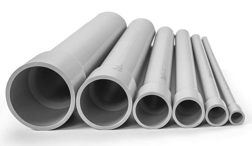
من بين الأنواع المختلفة من المواسير المتاحة، تبرز المواسير الكهربائية الصلبة بفضل متانتها وملاءمتها للتطبيقات الصناعية والسكنية على حد سواء.
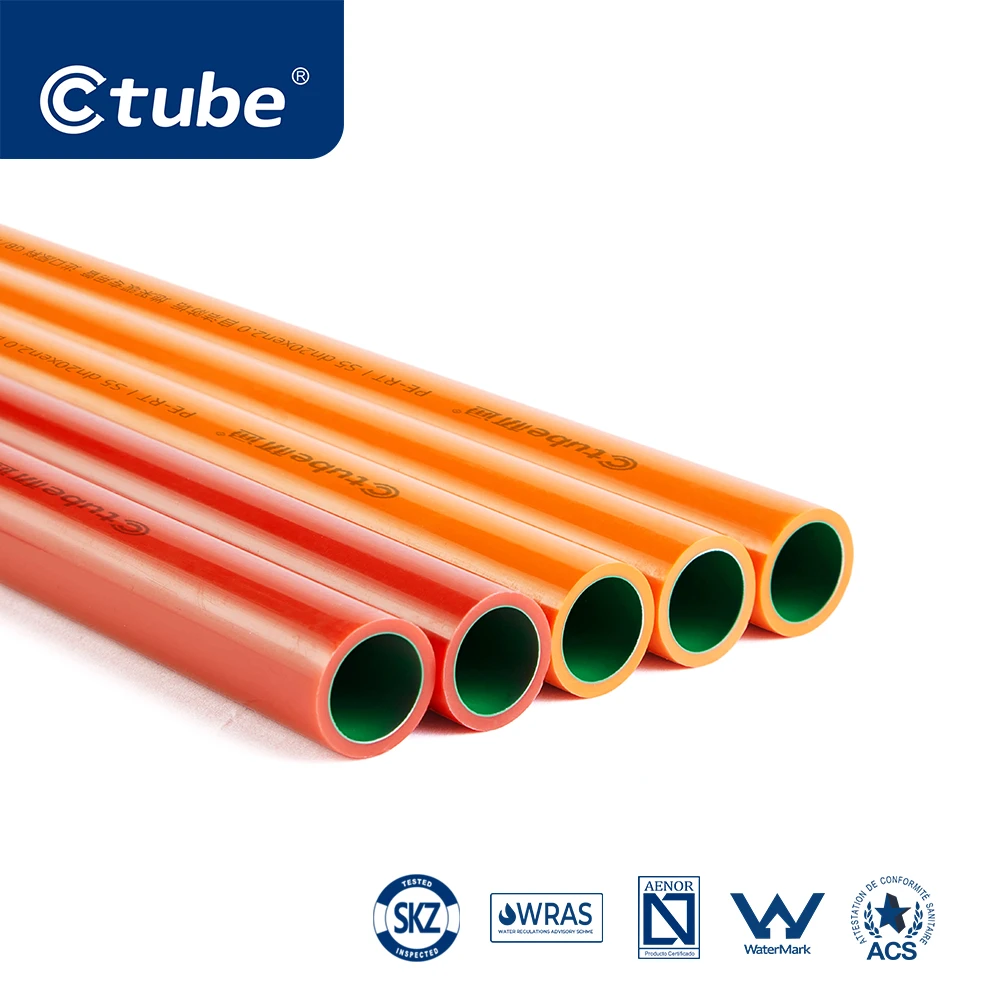
تتوفر أنابيب التوصيل الكهربائية الصلبة بأشكال متنوعة، كل منها مصمم لتلبية احتياجات محددة حسب المادة والتطبيق. تشمل المواد الأساسية المستخدمة في تصنيعها PVC (كلوريد البولي فينيل)، والفولاذ المجلفن، والألومنيوم، وRTRC (أنابيب الراتنج المقوى بالحرارة)، وغيرها. تتميز كل مادة بمزايا فريدة، مما يجعل أنابيب التوصيل الصلبة متعددة الاستخدامات في بيئات ومتطلبات مشاريع متنوعة. بنهاية هذا المقال، ستكون لديك معرفة شاملة بأنابيب التوصيل الكهربائية الصلبة، ولماذا تُعد مكونًا أساسيًا في الأنظمة الكهربائية الحديثة، وكيفية دمجها في مشروعك القادم لضمان أعلى مستويات السلامة والكفاءة والامتثال.
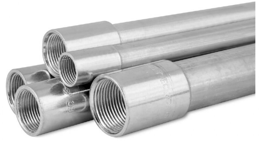
قناة معدنية صلبة وتشمل أنواعًا مثل الأنابيب المعدنية الصلبة (RMC) والأنابيب المعدنية المتوسطة (IMC) والأنابيب المعدنية الكهربائية (EMT)، والمعروفة بقوتها ومتانتها، مما يجعلها مناسبة للاستخدام الصناعي والخارجي.أنبوب بلاستيكي صلب, إن المواد مثل البولي فينيل كلوريد الصلب (PVC) خفيفة الوزن ومقاومة للتآكل، وتستخدم عادة في البيئات التي تكون فيها الحماية من الرطوبة ضرورية، مثل المنشآت تحت الأرض.
بالإضافة إلى ذلك،, قناة RTRC, يوفر هذا المنتج المصنوع من الألياف الزجاجية عزلًا كهربائيًا ممتازًا ومقاومة حرارية وحماية من التآكل، مما يجعله خيارًا مثاليًا للتطبيقات التي تتطلب مواد غير موصلة وعالية القوة.
في المقالة التالية، سوف نقدم تفاصيل الأنابيب الصلبة المصنوعة من مواد مختلفة.
2. أنواع المواسير الكهربائية الصلبة - مقدمة تفصيلية
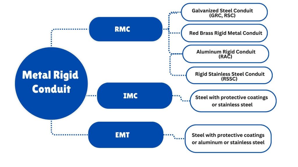
يتوفر RMC في المواد التالية:
• فولاذ مطلي بطبقات واقية
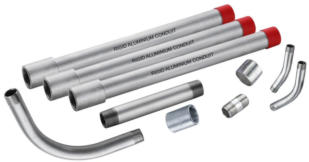
• الألومنيوم
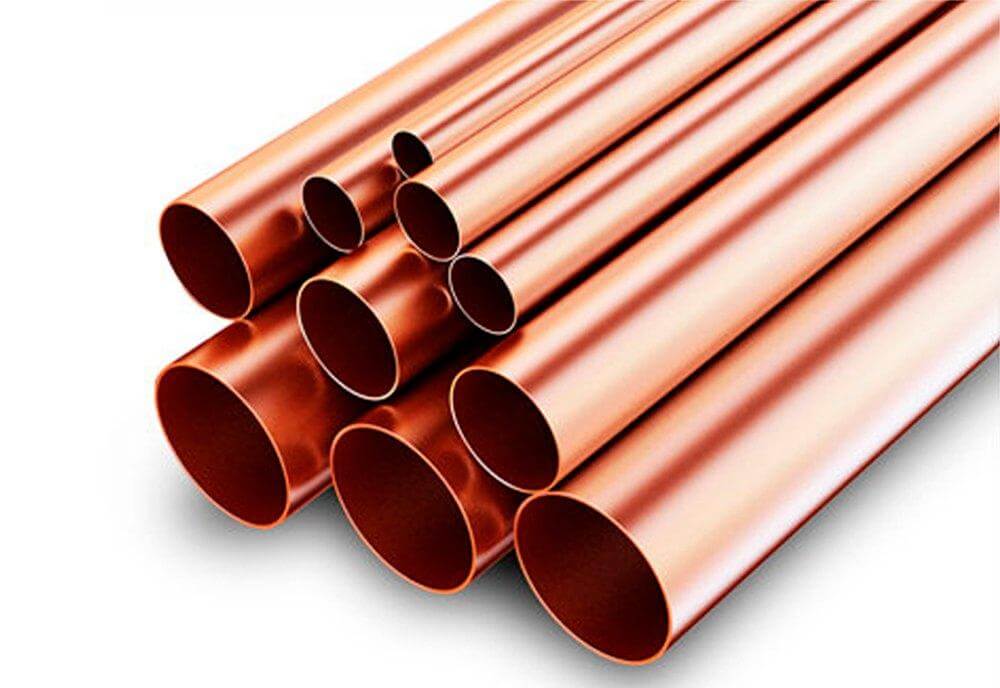
• نحاس أحمر
• الفولاذ المقاوم للصدأ
المادة والهيكل
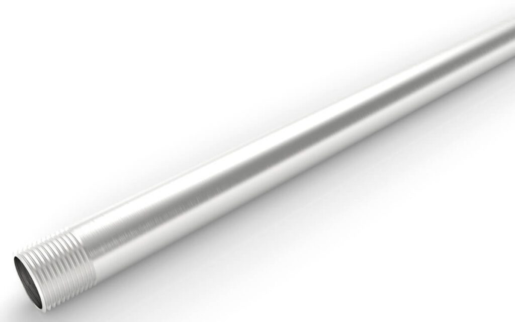
يجب أن يكون كل أنبوب يستخدم في قناة الصلب الصلبة (RSC) مصنوعًا من الفولاذ، مما يضمن أنه مستقيم ويتميز بمقطع عرضي دائري.
| مُعرِّف متري | القطر الخارجي (مم) | حجم تجاري | القطر الخارجي،, a (في) |
|---|---|---|---|
| 12b | 17.15 | 3/8b | 0.675 |
| 16 | 21.34 | 1/2 | 0.840 |
| 21 | 26.67 | 3/4 | 1.050 |
| 27 | 33.40 | 1 | 1.315 |
| 35 | 42.16 | 1-1/4 | 1.660 |
| 41 | 48.26 | 1-1/2 | 1.900 |
| 53 | 60.33 | 2 | 2.375 |
| 63 | 73.03 | 2-1/2 | 2.875 |
| 78 | 88.90 | 3 | 3.500 |
| 91 | 101.60 | 3-1/2 | 4.000 |
| 103 | 114.30 | 4 | 4.500 |
| 129 | 141.30 | 5 | 5.563 |
| 155 | 168.28 | 6 | 6.625 |
a التفاوتات المسموح بها: المقاس التجاري 12-41 (3/8-1-1/2) ± 0.38 مم (±0.015 بوصة). المقاس التجاري 53-155 (2-6) ± 1%.
b في الولايات المتحدة، يُسمح باستخدام مقاس 12 (3/8) في تطبيقات خاصة. أما في كندا، فلا يُسمح باستخدام هذا المقاس وفقًا لقانون الكهرباء الكندي، الجزء الأول.
اللحامات الملحومة
يجب أن تستوفي عملية لحام أنابيب الخرسانة المسلحة معايير صارمة لضمان السلامة والفعالية.
يجب ألا تحتوي اللحامات الملحومة على حواف معدنية أو حواف حادة أو نتوءات قد تتداخل مع الأسلاك الداخلية أو عملية التركيب.
يُسمح بوجود حافة صغيرة على طول الجزء الداخلي من الدرزة، طالما أنها ناعمة ولا تتجاوز 0.38 مم (0.015 بوصة) في الارتفاع للأحجام التجارية من 12 إلى 53 (من 3/8 بوصة إلى 2 بوصة) أو 0.51 مم (0.020 بوصة) للأحجام التجارية من 63 إلى 155 (من 2 ½ بوصة إلى 6 بوصات).
متطلبات الطول والوزن القياسية
يجب أن يتبع الطول القياسي للأنابيب المستقيمة المطلية بالزنك أو الأنابيب الملولبة العارية المراد طلاؤها بمادة بديلة مقاومة للتآكل، بما في ذلك وصلة واحدة، المواصفات المفصلة في الجدول التالي.
توضح هذه الجداول أبعاد وأوزان الأنابيب التي تتوافق مع المعايير المحددة.
| مُعرِّف متري | طول الأنبوب المستقيمa (مم) |
الحد الأدنى للوزن المقبول لعشرة أطوال من الأنابيب مع عشرة وصلات (كجم) قناة مطلية بالزنكb |
الحد الأدنى للوزن المقبول لعشرة أطوال من الأنابيب مع عشرة وصلات (كجم) أنبوب ملولب مكشوفc |
حجم تجاري | طول الأنبوب المستقيم القدم والبوصةa ±1/4 |
الحد الأدنى للوزن المقبول لعشرة أطوال من الأنابيب مع عشرة وصلات (بالرطل) قناة مطلية بالزنكb |
الحد الأدنى للوزن المقبول لعشرة أطوال من الأنابيب مع عشرة وصلات (بالرطل) أنبوب ملولب مكشوفc |
|---|---|---|---|---|---|---|---|
| 12d | 3035 | 23.4 | 22.6 | 3/8 | 9′–11 1/2″ | 51.5 | 48.6 |
| 16 | 3030 | 35.8 | 34.4 | 1/2 | 9′–11″ | 78.9 | 75.8 |
| 21 | 3030 | 47.6 | 45.5 | 3/4 | 9′–11″ | 104.9 | 100.3 |
| 27 | 3030 | 69.4 | 65.8 | 1 | 9′–11″ | 153.0 | 145.1 |
| 35 | 3025 | 91.2 | 87.8 | 1-1/4 | 9′–11″ | 201.0 | 193.5 |
| 41 | 3025 | 112.9 | 109.4 | 1-1/2 | 9′–11″ | 249.0 | 241.2 |
| 53 | 3035 | 150.4 | 144.3 | 2 | 9′–11 1/2″ | 331.6 | 318.1 |
| 63 | 3010 | 209.6 | 203.4 | 2-1/2 | 9′–10 1/4″ | 462.0 | 448.4 |
| 78 | 3010 | 239.0 | 233.4 | 3 | 9′–10 1/4″ | 527.0 | 514.8 |
| 91 | 3010 | 274.1 | 268.4 | 3-1/2 | 9′–10 1/4″ | 604.4 | 591.5 |
| 103 | 2995 | 312.0 | 305.3 | 4 | 9′–10″ | 687.6 | 672.9 |
| 129 | 2995 | 591.7 | 578.6 | 5 | 9′–10″ | 1304.9 | 1275.6 |
| 155 | 2995 | 797.1 | 781.4 | 6 | 9′–10″ | 1757.0 | 1722.7 |
a تم تصميم الأطوال المشار إليها لإنتاج طول 3.05 متر (10 قدم) من الأنابيب عند توصيل وصلة الأنابيب ذات الفتحة المستقيمة.
b هذا الأنبوب محمي بطبقة من الزنك أو طبقة أساسها الزنك تتكون أساسًا من الزنك.
c يهدف هذا الأنبوب إلى حمايته بطبقة بديلة مقاومة للتآكل.
d في الولايات المتحدة، يُسمح باستخدام مقاس 12 (3/8) في تطبيقات خاصة. أما في كندا، فلا يُسمح باستخدام هذا المقاس وفقًا لقانون الكهرباء الكندي، الجزء الأول.
متطلبات الاختبار
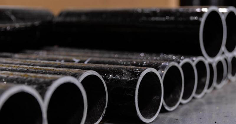
اختبار الأنابيب من الأنابيب الفولاذية الصلبة
تتضمن عملية اختبار الأنابيب ثني عينة من أصغر حجم تجاري متاح على شكل ربع دائرة حول مغزل، أولاً في درجة حرارة الغرفة ثم بعد تهيئتها عند 0 درجة مئوية (32 درجة فهرنهايت) لمدة 60 دقيقة.
يجب ألا يتشقق الأنبوب أو ينكسر لحامه. إذا كان الأنبوب مطليًا بطبقة غير معدنية ومصممًا لتحمل درجات حرارة أقل من 0 درجة مئوية، يُجرى الاختبار عند تلك الدرجة المنخفضة.
| الطلاءات | الاختبارات | البند # |
|---|---|---|
| الزنك | اختبار الانحناء كولد بيند اختبار طلاء الزنك |
6.2.1.1 6.2.1.3 6.2.2 |
| مقاوم للتآكل بديل | اختبار الانحناء كولد بيند الأشعة فوق البنفسجية والماء رذاذ الملح (الضباب) ثاني أكسيد الكربون الرطب - ثاني أكسيد الكبريت - الهواء الشد التصاق انتشار اللهب |
6.2.1.1 6.2.1.3 6.2.4.3 6.2.4.5 6.2.4.6 6.2.4.8 6.2.4.9 6.2.4.11 |
| بديل غير معدني مقاوم للتآكل (بالإضافة إلى ما سبق) | التجميع، الانحناء، المقاومة، السحب، وتيار العطل استمرارية التيار الكهربائي تحديد المركبات تأثير البرد |
5.3.3.2 5.3.5.2 6.2.1.5 6.2.1.0 |
| عضوي | اختبار الانحناء كولد بيند تحديد المركبات مرونة اختبار الهواء الدافئ الرطب |
6.2.1.1 6.2.1.3 6.2.1.5 6.2.3.5 6.2.3.2 |
| الطلاءات التكميلية | الآثار الضارة على الطلاء الأساسي ملاءمة الوصلات استمرارية التيار الكهربائي انتشار اللهب |
5.3.5.2 5.3.5.2 5.3.5.2 6.2.4.11 |
| معالجة السطح | غير متوفر إذا كان سمكها أقل من 0.038 مم (0.00015 بوصة) | 5.3.6.1 |
اختبار طلاء الأنابيب الفولاذية الصلبة
يوضح الجدول التالي اختبارات مختلفة لأنواع مختلفة من الطلاءات المطبقة على الأنابيب، بما في ذلك الزنك، والطلاءات البديلة المقاومة للتآكل، والطلاءات غير المعدنية، والطلاءات العضوية، والطلاءات التكميلية.
تقيّم هذه الاختبارات أداء الطلاء في ظل ظروف مختلفة مثل الانحناء، والتعرض للأشعة فوق البنفسجية، ورذاذ الملح، ودرجات الحرارة المنخفضة، والاستمرارية الكهربائية.
قناة سلكية من الفولاذ المقاوم للصدأ قابلة للربط ذات مقطع عرضي دائري مصممة للحماية المادية وتوجيه موصلات الأسلاك واستخدامها كموصل تأريض للمعدات عند تركيبها باستخدام التركيبات المناسبة.
قناة معدنية صلبة كهربائية - نحاس أحمر (ERMC-RB)
قناة معدنية صلبة كهربائية - ألومنيوم (ERMC-A)
| حجم تجاري | القطر الداخلي الاسمي (بوصة) | القطر الخارجي (بوصة) | سُمك الجدار (بوصة) | الطول بدون وصلة (قدم وبوصة) | الحد الأدنى للوزن (10 قطع مع وصلات) (رطل) |
|---|---|---|---|---|---|
| 1/2 | 0.632 | 0.840 | 0.104 | 9'11-1/4" | 27.4 |
| 3/4 | 0.836 | 1.050 | 0.107 | 9'11-1/4" | 36.4 |
| 1 | 1.063 | 1.315 | 0.126 | 9'11"’ | 50.7 |
| 1-1/4 | 1.394 | 1.660 | 0.138 | 9'11"’ | 66.2 |
| 1-1/2 | 1.624 | 1.900 | 0.138 | 9'11"’ | 86.2 |
| 2 | 2.067 | 2.375 | 0.154 | 9'10-1/2" | 125.0 |
| 2-1/2 | 2.489 | 2.875 | 0.193 | 9'10-1/2" | 182.5 |
| 3 | 3.068 | 3.500 | 0.225 | 9'10-1/4" | 236.8 |
| 3-1/2 | 3.570 | 4.000 | 0.245 | 9'10-1/4" | 358.7 |
| 4 | 4.032 | 4.500 | 0.265 | 9'10"’ | 454.9 |
| 5 | 5.073 | 5.563 | 0.245 | 9'10"’ | 454.9 |
| 6 | 6.093 | 6.625 | 0.266 | 9'10"’ | 604.4 |
| حجم تجاري | القطر الخارجي (بوصة) الأعلى |
القطر الخارجي (بوصة) مين |
سُمك الجدار (بوصة) الأعلى |
سُمك الجدار (بوصة) مين |
القطر الداخلي الاسمي (بوصة) | الطول بدون وصلة (قدم وبوصة) |
|---|---|---|---|---|---|---|
| 1/2 | 0.820 | 0.810 | 0.085 | 0.070 | 0.659 | 9'11-1/4" |
| 3/4 | 1.034 | 1.024 | 0.090 | 0.075 | 0.863 | 9'11-1/4" |
| 1 | 1.295 | 1.285 | 0.100 | 0.085 | 1.063 | 9'11"’ |
| 1-1/4 | 1.645 | 1.630 | 0.105 | 0.085 | 1.448 | 9'11"’ |
| 1-1/2 | 1.890 | 1.875 | 0.115 | 0.090 | 1.683 | 9'11"’ |
| 2 | 2.367 | 2.352 | 0.115 | 0.095 | 2.150 | 9'11"’ |
| 2-1/2 | 2.867 | 2.847 | 0.160 | 0.140 | 2.575 | 9'10-1/2" |
| 3 | 3.486 | 3.466 | 0.160 | 0.140 | 3.176 | 9'10-1/2" |
| 3-1/2 | 3.981 | 3.961 | 0.160 | 0.140 | 4.161 | 9'10-1/4" |
| 4 | 4.476 | 4.456 | 0.160 | 0.140 | 4.166 | 9'10-1/4" |
• فولاذ مطلي بطبقات واقية
• الألومنيوم
يجب طلاء السطح الداخلي إما بالزنك أو بطلاء عضوي. ويجب أن يحافظ هذا الطلاء الداخلي على سطح أملس ومتواصل، مع مراعاة الاختلافات الطفيفة الناتجة عن تدفق الطلاء غير المتساوي.
| حجم تجاري | مُعرِّف متري | أقصى طول (قدم) | أقصى طول (م) |
|---|---|---|---|
| نصف - ثلاثة أرباع | 16 – 21 | 10′ 1/4″ | 3.05 |
| 1 – 2 | 27 – 53 | 15 قدمًا وربع بوصة | 4.58 |
| 2-1/2 – 4 | 63 – 103 | 20 قدمًا وربع بوصة | 6.10 |
المادة 342 ذكرت مادة الأنابيب المعدنية الوسيطةيتوفر t IMC في المواد التالية:
- فولاذ مع طبقات واقية
- الألومنيوم
| حجم تجاري | مُعرِّف متري | القطر الخارجي (بوصة) | القطر الداخلي (بوصة) | سُمك الجدار (بوصة) | الحد الأدنى لوزن الألومنيوم (رطل/قدم مكعب) | الحد الأدنى لوزن الفولاذ المقاوم للصدأ (رطل/قدم) |
|---|---|---|---|---|---|---|
| 1/2 | 16 | 0.705 ±0.005 | 0.622 | 0.042 | 0.099 | 0.300 |
| 3/4 | 21 | 0.922 ±0.005 | 0.824 | 0.049 | 0.159 | 0.500 |
| 1 | 27 | 1.163 ±0.005 | 1.049 | 0.057 | 0.221 | 0.700 |
| 1-1/4 | 35 | 1.510 ±0.005 | 1.380 | 0.065 | 0.381 | 1.100 |
| 1-1/2 | 41 | 1.740 ±0.005 | 1.610 | 0.065 | 0.430 | 1.200 |
| 2 | 53 | 2.197 ±0.005 | 2.067 | 0.065 | 0.484 | 1.380 |
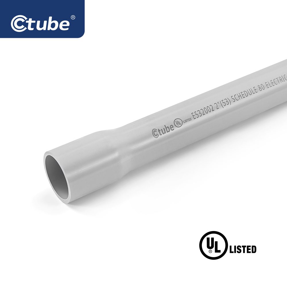
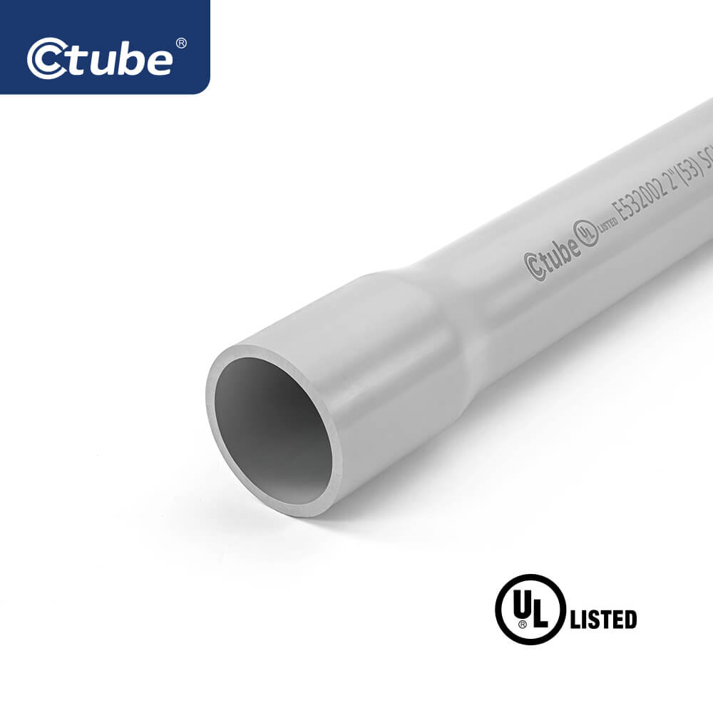
اختبار أنابيب PVC الصلبة
تتميز أنابيب الجدول 40 والجدول 80 بأقطار خارجية محددة وسماكات جدارية دنيا لكل مقاس تجاري. وهذا يضمن السلامة الهيكلية لمختلف التطبيقات.
تُختبر عينات المواسير وفقًا لمعيار ASTM D 638. يجب أن تحتفظ العينات القديمة بنسبة 95% من قوة الشد للعينات غير القديمة. الحد الأدنى للقوة هو 5000 رطل لكل بوصة مربعة للجدول 40/80، و4000 رطل لكل بوصة مربعة للمواسير من النوع A وEB.
يتم اختبار عشر عينات من الأنابيب بطول 6 بوصات باستخدام أوزان ساقطة. لا يجوز أن تتشقق أو تتمزق أكثر من ثلاث عينات منها بما يتجاوز 1/32 بوصة. تُستخدم أوزان مختلفة: 20 رطلاً للأنابيب من النوع SCH 40، والنوع A، والنوع EB؛ و75 رطلاً للأنابيب من النوع SCH 80.
يجب أن تنطفئ الأنابيب ذاتيًا في غضون 5 ثوانٍ من تعرضها للهب، وألا تتسبب في اشتعال المواد المجاورة. يشبه هذا الاختبار تصنيف UL 94 V-0، الذي يتطلب مقاومة عالية للهب وعدم وجود أي قطرات مشتعلة.
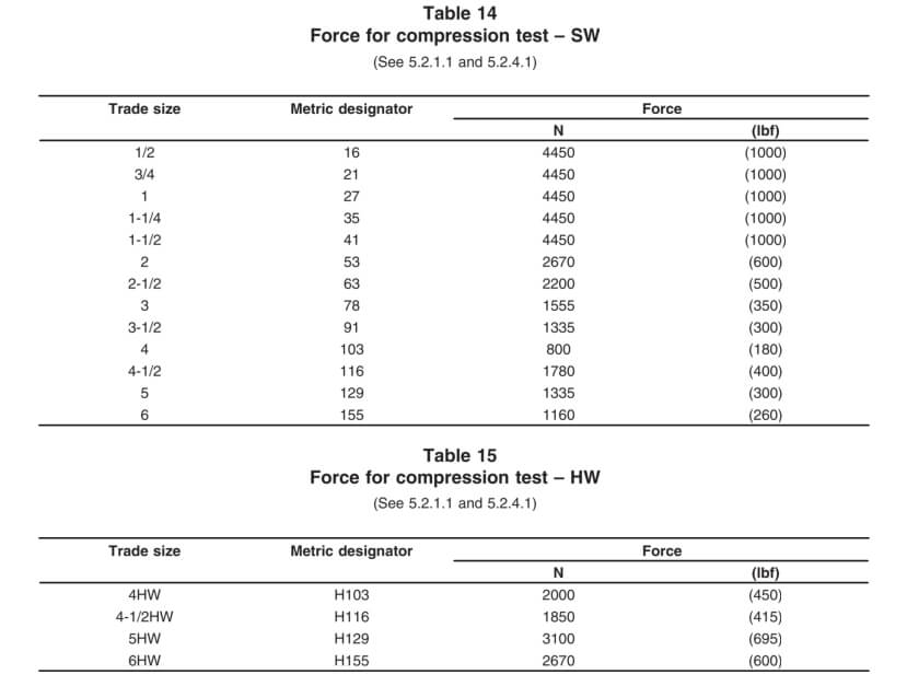
يجب ألا تتشوه الأنابيب أو تنفصل تحت الضغط بين الصفائح الفولاذية. يجب أن تحافظ العينات المسطحة على قطر داخلي لا يقل عن 70% من قطرها الأصلي.
تقيس مقاومة الانضغاط قدرة المادة على تحمل قوى الضغط الثابتة (مثل ضغط التربة). أما مقاومة الصدمات فتقيس استجابة المادة للصدمات أو السقوط المفاجئ. وكلاهما بالغ الأهمية في مختلف الظروف الميدانية.
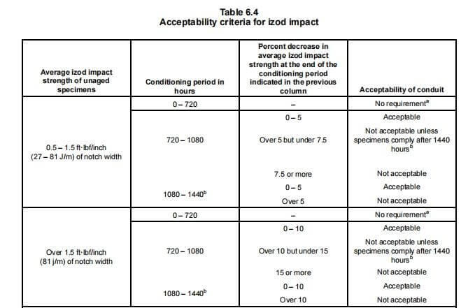
بالنسبة للجدولين 40 و80، يتضمن اختبار التعرض لأشعة الشمس اختبار قوة الصدمة وفقًا لمعيار إيزود (≥0.5 قدم-رطل/بوصة). تُختبر العينات على مدى فترات تتراوح بين 720 و1440 ساعة وفقًا لطرق ASTM D 256 لضمان متانتها في ظروف الأشعة فوق البنفسجية.
يتم تحديد الأنواع حسب نظام القطر وسماكة الجدار:
- بطاقة تعريف: القطر الداخلي
- نظام تحديد المواقع الدولي (IPS): حجم أنبوب الحديد (القطر الخارجي)
- سُمك الجدار: SW (قياسي)، MW (متوسط)، HW (ثقيل)، XW (ثقيل جدًا)

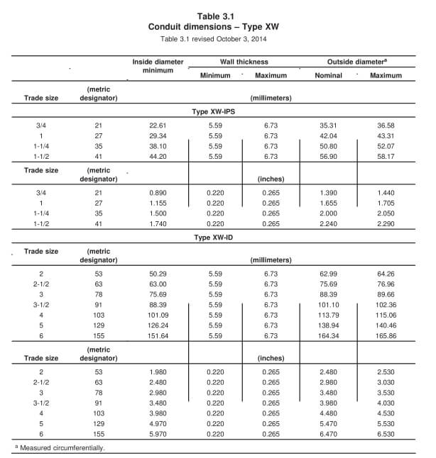
التطبيقات:
- فوق الأرض: يو ال 2515
- مترو الأنفاق: يو ال 2420
يتم اختبار كل عينة من حيث مدة ما بعد اللهب: يجب ألا يتجاوز الاشتعال 30 ثانية بعد أول أربع تطبيقات للهب، ولا 60 ثانية بعد التطبيق الخامس.
الاختياري FT4 يُعد اختبار اللهب أحد أكثر الاختبارات صرامة، وهو مطلوب في بعض الإنشاءات الكندية غير القابلة للاحتراق. ويتضمن تعريض المواد لـ 70,000 وحدة حرارية بريطانية/ساعة أشعل النار لمدة 20 دقيقة.
معايير النجاح: يجب ألا يتجاوز طول الجزء المتفحم 1.5 متر (5 أقدام) من أسفل الموقد (CSA C22.2 رقم 38).
اختبارات التأهيل لأنابيب الراتنج المقوى بالحرارة (RTRC)
3. دراسة متطلبات عمق الدفن للأنابيب الكهربائية الصلبة
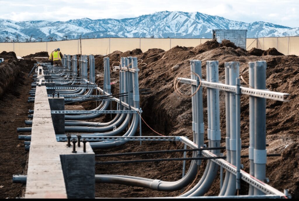
في مجال التركيبات الكهربائية، يعد عمق الدفن المناسب للأنابيب أمرًا بالغ الأهمية لضمان السلامة والامتثال والمتانة. تتطلب الأنابيب الكهربائية الصلبة، بما في ذلك الأنابيب المعدنية الصلبة (RMC)، والأنابيب غير المعدنية مثل أنابيب البولي فينيل كلوريد (PVC)، والأنابيب المصنوعة من الألياف الزجاجية، متطلبات عمق دفن محددة تمليها كل من قانون الكهرباء الوطني (NEC) وأكواد البناء المحلية.
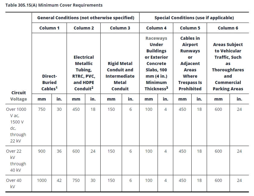
ملحوظات:
1. غطاء يُعرَّف بأنه أقصر مسافة بالملليمترات (البوصات) مقاسة بين نقطة على السطح العلوي لأي موصل مدفون مباشرة أو كابل أو قناة أو مجرى آخر والسطح العلوي للأرضية النهائية أو الخرسانة أو غطاء مماثل.
2. يُسمح بأعماق أقل عندما ترتفع الكابلات والموصلات من أجل النهايات أو الوصلات أو عندما يكون الوصول مطلوبًا بطريقة أخرى.
3. في حال حالت الصخور الصلبة دون الالتزام بأعماق التغطية المحددة في هذا الجدول، يجب تركيب الأسلاك في مجرى معدني أو غير معدني مُرخص للدفن المباشر. ويجب تغطية المجاري بطبقة خرسانية لا تقل سماكتها عن 50 مم (بوصتين) تمتد حتى الصخور.
4. في المنشآت الصناعية، حيث تضمن شروط الصيانة والإشراف أن يقوم أشخاص مؤهلون بصيانة التركيب، يُسمح بتقليل الحد الأدنى لمتطلبات الغطاء للأنابيب المعدنية غير الصلبة والأنابيب المعدنية المتوسطة بمقدار 150 مم (6 بوصات) لكل 50 مم (2 بوصة) من الخرسانة أو ما يعادلها الموضوعة بالكامل داخل الخندق فوق التركيب تحت الأرض.
5. الكابلات المدفونة مباشرة: يجب تحديد موقع الكابلات المدفونة تحت الأرض مباشرة والتي لا يتم تغليفها أو حمايتها بالخرسانة والمدفونة على عمق 750 مم (30 بوصة) أو أكثر تحت مستوى الأرض بواسطة شريط تحذيري يوضع في الخندق على بعد 300 مم (12 بوصة) على الأقل فوق الكابلات.
6. أنابيب معدنية كهربائية، وأنابيب RTRC، وأنابيب PVC، وأنابيب HDPE: قد تُدرج هذه الأنظمة من قِبل جهة اختبار معتمدة على أنها مناسبة للدفن المباشر دون تغليف. أما جميع الأنظمة غير المعدنية الأخرى، فيجب أن تتطلب طبقة من الخرسانة بسمك 50 مم (2 بوصة) أو ما يعادلها فوق القناة، بالإضافة إلى عمق سطحها.
7. قنوات الكابلات تحت المباني أو الألواح الخرسانية الخارجية (بسماكة لا تقل عن 100 مم / 4 بوصات): يجب أن تمتد البلاطة مسافة لا تقل عن 150 مم (6 بوصات) خارج التركيب تحت الأرض، ويجب وضع شريط تحذير أو أي وسيلة فعالة أخرى مناسبة للظروف فوق التركيب تحت الأرض.
8. يجب تركيب الكابلات الأخرى غير المحمية التي لم يتم تغطيتها في 305.15 (أ) (1) أو (أ) (2) في قناة معدنية صلبة، أو قناة معدنية متوسطة، أو قناة غير معدنية صلبة مغلفة بما لا يقل عن 75 مم (3 بوصات) من الخرسانة.
9. ظهور الموصلات من الأرض: يجب وضع هذه الأسلاك داخل قنوات معتمدة. يجب أن تكون القنوات المثبتة على الأعمدة مصنوعة من أنابيب معدنية صلبة، أو أنابيب معدنية متوسطة، أو أنابيب RTRC-XW، أو أنابيب PVC من الجدول 80، أو ما يعادلها، وتمتد من الحد الأدنى لعمق الغطاء المحدد في الجدول 305.15 (أ) إلى نقطة على ارتفاع 2.5 متر (8 أقدام) فوق مستوى الأرض النهائي.
تؤثر العوامل البيئية بشكل كبير على عمق دفن الأنابيب. يمكن لظروف التربة، مثل الاستقرار ومحتوى الرطوبة، أن تحدد مدى عمق تثبيت الأنابيب لضمان بقائها آمنة بمرور الوقت. على سبيل المثال، في التربة الصخرية أو غير المستقرة، قد يكون الدفن على عمق أكبر ضروريًا لمنع الضرر الناتج عن حركة التربة.
تلعب أحمال المرور أيضًا دورًا بالغ الأهمية، وخاصة في المناطق التي يتم فيها تركيب الأنابيب أسفل الطرق أو مواقف السيارات. وهنا، غالبًا ما تكون هناك حاجة إلى دفن الأنابيب بشكل أعمق لحماية الأنابيب من وزن واهتزاز المركبات والمعدات الثقيلة.
4. إرشادات تركيب أنواع مختلفة من المواسير الصلبة
قبل البدء، قم بجمع الأدوات والمواد التالية:
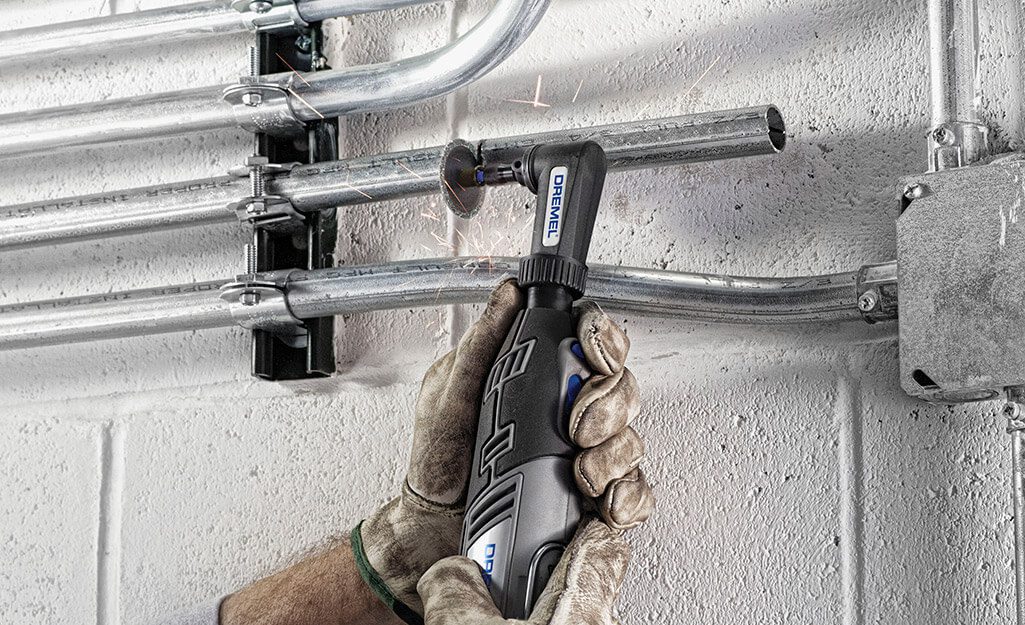
• أدوات القطع: منشارا يدويا أو قاطعا أسطوانيا (إذا كان القطع مطلوبا).
• مخرطة: لإزالة النتوءات الموجودة داخل الأنبوب بعد القطع.
• ثني الأنابيب: لإجراء انحناءات دقيقة.
• مفاتيح: الحجم مناسب.
• مركب مانع للتسرب أو طلاء مقاوم للتآكل: لحماية الخيوط إذا لزم الأمر.
تأكد أيضًا من أن لديك جميع التركيبات والوصلات والموصلات اللازمة لضمان التأريض المناسب.
• القياس والقطع: قم بقياس الطول المطلوب ثم قم بقصه بشكل نظيف باستخدام المنشار.
• رزمة: قم بإزالة النتوءات الموجودة داخل الأنبوب لتجنب تلف الأسلاك.
• الخيوط: استخدم قالبًا قياسيًا (NPT) بقياس ¾ بوصة لكل قدم للخيوط عند الحاجة. يجب أن تكون الخيوط ناعمة ونظيفة.
بالنسبة للأنابيب الملولبة مسبقًا، قم بتخطي عملية الترابط ولكن قم بحماية الخيوط المكشوفة أو التالفة.
• شد يدوي وربط بالمفتاح: ابدأ بالربط يدويًا، ثم قم بالربط باستخدام مفتاح الربط عادةً بعد دورة كاملة من الربط اليدوي.
• تجنب الإفراط في الشد: قد يؤدي الإفراط في استخدام القوة إلى إتلاف الخيوط والطلاء. لا تستخدم وصلات مفاتيح الربط.
• بالنسبة للتجهيزات غير الملولبة، ادفع الأنبوب بالكامل داخل التجهيز وقم بتثبيته بعزم دوران مناسب.
• ثني اليد: يمكن ثني الأحجام الصغيرة (من ½ إلى 1 بوصة) باستخدام أداة ثني يدوية؛ وتتطلب الأحجام الأكبر استخدام أدوات ثني ميكانيكية أو كهربائية.
• دقة: قم بوضع علامة على الانحناءات؛ وتجنب تجاوز 90 درجة بين نقاط السحب.
• تجنب العقد: منع التسطيح أو الالتواء، مما يقلل المساحة ويجعل عملية سحب الأسلاك معقدة.
• بالنسبة للأنابيب الملولبة مسبقًا، تجنب إتلاف الخيوط أثناء الانحناء.
• استخدم الأشرطة أو الشماعات أو المشابك لتثبيت الأنابيب على الجدران أو الأسقف أو العناصر الهيكلية.
• بالنسبة للمسارات الرأسية، قم بتأمين القناة في الطرف العلوي لمنع الترهل.
• بالنسبة للقنوات التي تنتقل من الخرسانة إلى التربة أو تحت الأرض، ضع الطلاءات المعتمدة أو الأغلفة أو القنوات المغطاة بالـ PVC للحصول على حماية إضافية.
• فحص الطلاءات المطبقة في المصنع بحثًا عن أي تلف أثناء التثبيت.
• استخدم المركبات المقاومة للتآكل، أو الطلاء الغني بالزنك، أو الشريط المقاوم للتآكل حسب الحاجة.
• حماية الخيوط المقطوعة ميدانيًا باستخدام الطلاءات المقاومة للتآكل والموصلة للكهرباء.
• إجراء اختبار الاستمرارية للتأكد من استمرارية الكهرباء والتأريض.
• فحص جميع توصيلات الأنابيب للتأكد من إحكامها وتأمين الدعامات.
• التحقق من بقاء الطلاءات الواقية سليمة وتطبيق الحماية الإضافية حسب الضرورة.
قبل أن تبدأ، قم بجمع الأدوات والمواد اللازمة لتثبيت قناة PVC بنجاح:
أنابيب PVC: القطر والطول المناسبين لمشروعك.
تجهيزات PVC: وصلات، وأكواع، وصناديق الوصلات، ومكونات أخرى.
أسمنت وطبقة أولية من البولي فينيل كلوريد: لتأمين الوصلات والتجهيزات.
قاطع الأنابيب أو المنشار المعدني: لقطع الأنابيب إلى الطول المطلوب.
أداة إزالة النتوءات: لتنعيم حواف القطع في الأنبوب.
شريط القياس: للحصول على قياسات دقيقة.
المستوى: لضمان المحاذاة الصحيحة.
سحب الخيط أو شريط السمك: لسحب الأسلاك عبر القناة بعد التثبيت.
قبل البدء في التركيب، قم بالتخطيط بعناية لمسار أنبوب PVC الخاص بك. يتضمن ذلك قياس المسافة بين النقاط التي سيمر بها الأنبوب ورسم خريطة للأماكن التي ستكون هناك حاجة فيها إلى الانحناءات والتجهيزات والوصلات.
القياس والعلامة: استخدم شريط قياس لتحديد طول أنبوب PVC المطلوب لكل قسم ووضع علامة على أماكن إجراء القطع.
خذ في الاعتبار التمدد والانكماش: يتمدد أنبوب PVC وينكمش مع تغيرات درجة الحرارة، لذا ستحتاج إلى ترك بعض المساحة للحركة أو تثبيت تجهيزات التمدد في المسافات الطويلة.
إن قطع أنابيب PVC أسهل بكثير من قطع الأنابيب المعدنية، ولكن لا يزال من المهم إجراء قطع نظيفة ودقيقة لضمان التركيب السلس.
قطع الأنابيب: استخدم قاطع أنابيب من مادة البولي فينيل كلوريد أو منشارًا دقيق الأسنان لقطع الأنابيب إلى الأطوال المقاسة. تأكد من أن القطع مستقيمة ونظيفة.
إزالة النتوءات من الحواف: بعد القطع، استخدم أداة إزالة النتوءات أو سكينًا متعدد الاستخدامات لإزالة أي حواف خشنة أو نتوءات من داخل وخارج الأنبوب. هذه الخطوة ضرورية لمنع إتلاف الأسلاك عند سحبها عبر الأنبوب.
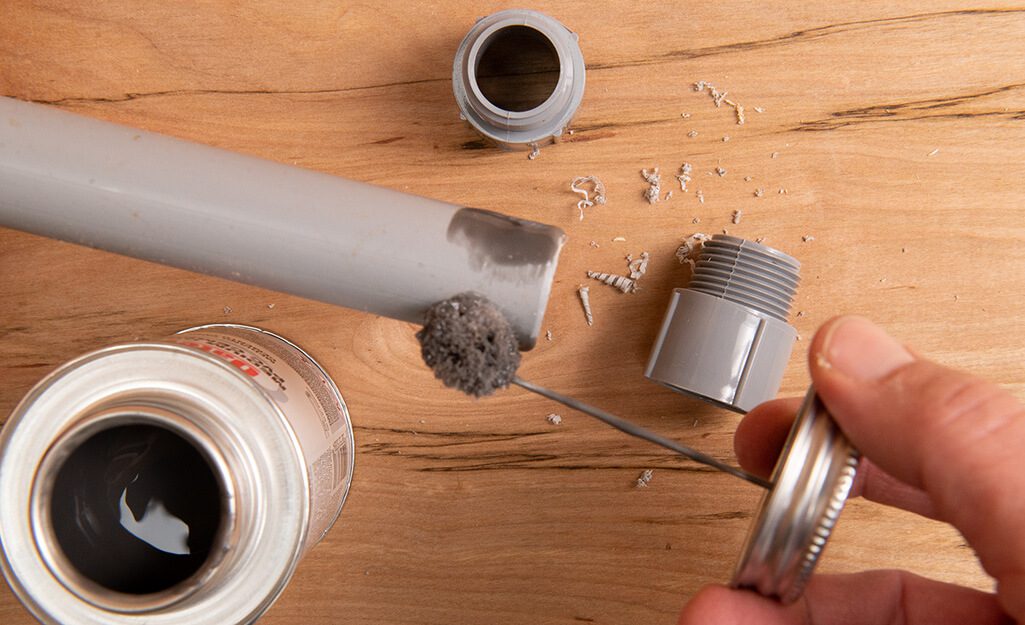
على عكس الأنابيب المعدنية، حيث يتم استخدام الخيوط أو التركيبات اللولبية، يتم ربط أقسام الأنابيب البلاستيكية من خلال عملية تسمى اللحام بالمذيبات. تتضمن هذه العملية استخدام مادة أولية وأسمنت من البولي فينيل كلوريد لربط الأنابيب والتركيبات معًا.
استخدم البرايمر: أولاً، نظف أطراف الأنابيب والجزء الداخلي من التركيبات باستخدام برايمر من مادة البولي فينيل كلوريد. يعمل البرايمر على تليين المادة وتجهيزها لعملية الترابط.
ضع أسمنت PVC: بعد وضع البرايمر مباشرة، قم بطلاء نفس المناطق بأسمنت PVC. تأكد من العمل بسرعة، حيث يجف الأسمنت بسرعة.
قم بربط الأنابيب والتجهيزات: ادفع الأنابيب داخل التجهيزة، مع لفها قليلاً لضمان انتشار الأسمنت بالتساوي. أمسك القطع معًا لبضع ثوانٍ لضمان الترابط القوي.
امسح الأسمنت الزائد: قم بإزالة أي أسمنت زائد يتسرب أثناء عملية التوصيل. اترك المفصل حتى يجف وفقًا لتعليمات الشركة المصنعة قبل التعامل معه بشكل أكبر.
تعمل عملية اللحام بالمذيبات هذه على إنشاء ختم مقاوم للماء، مما يجعل مادة PVC مثالية للتركيبات الخارجية وتحت الأرض حيث تكون مقاومة الرطوبة أمرًا بالغ الأهمية.
تختلف عملية ثني أنابيب PVC عن ثني الأنابيب المعدنية. يمكن ثني أنابيب PVC باستخدام الحرارة لإنشاء انحناءات ناعمة ومخصصة دون الحاجة إلى أكواع مسبقة الصنع في بعض المواقف.
تسخين أنبوب PVC: استخدم مسدسًا حراريًا أو سخانًا لثني أنبوب PVC لتسخين قسم الأنبوب حيث يلزم الثني. تأكد من توزيع الحرارة بالتساوي لتجنب تشوه الأنبوب.
قم بالثني: بمجرد أن يصبح الأنبوب مرنًا، قم بثنيه ببطء إلى الزاوية المطلوبة. ثبته في مكانه حتى يبرد الأنبوب ويحتفظ بشكله.
استخدم الأكواع المصنوعة مسبقًا: بالنسبة لمعظم التركيبات، يكون من الأسهل استخدام أكواع PVC المصنوعة في المصنع بزاوية 90 درجة أو 45 درجة، والتي يتم لصقها في مكانها باستخدام نفس عملية اللحام بالمذيبات.
نظرًا لأن مادة PVC أكثر مرونة وخفة وزن من الأنابيب المعدنية، فإنها تتطلب الدعم المناسب لمنع الترهل أو الحركة بمرور الوقت.
قم بتثبيت أحزمة أو مشابك الأنابيب: ادعم أنابيب PVC على فترات منتظمة عن طريق تأمينها بأحزمة أو مشابك الأنابيب. اتبع إرشادات NEC، التي توصي بدعم أنابيب PVC كل 3 إلى 6 أقدام، حسب قطر الأنابيب.
السماح بالتمدد: يتمدد أنبوب PVC وينكمش مع تغير درجات الحرارة. في المسافات الأطول، قم بتثبيت تجهيزات التمدد للسماح بالحركة دون إجهاد المفاصل. تعتبر تجهيزات التمدد ضرورية للتركيبات الخارجية أو المعرضة لأشعة الشمس حيث تكون التقلبات في درجات الحرارة كبيرة.
بعد تثبيت القناة وتثبيت وصلات الأسمنت، يمكنك سحب الأسلاك عبر القناة.
استخدم شريط صيد السمك أو خيط السحب: قم بتمرير شريط صيد السمك أو خيط السحب عبر مسار الموصل، ثم قم بتوصيل الأسلاك بشكل آمن بالشريط.
اسحب الأسلاك: اسحب الأسلاك ببطء عبر القناة، مع التأكد من عدم تعطلها أو تعرضها للتلف في أي حواف خشنة.
قم بالتشحيم إذا لزم الأمر: إذا كان مسار القناة طويلاً أو يحتوي على عدة انحناءات، فاستخدم مادة تشحيم سحب الأسلاك لتقليل الاحتكاك وتسهيل عملية سحب الأسلاك.
بمجرد سحب الأسلاك وإعداد النظام، قم بإجراء فحص نهائي للتأكد من تثبيت كل شيء بشكل صحيح وآمن.
التحقق من التوصيلات: تأكد من أن جميع الوصلات الملحومة بالمذيبات صلبة وأنه لم يتم فك أي من التركيبات.
التحقق من الدعامات: تأكد من أن جميع أحزمة التوصيل والمشابك متباعدة بشكل صحيح وآمنة.
لتثبيت مجرى RTRC بنجاح، قم بجمع الأدوات والمواد التالية:
- قناة RTRC: القطر المناسب وطول الأنابيب.
- تجهيزات RTRC: الوصلات والمرفقين والمكونات الضرورية الأخرى.
- إيبوكسي أو لاصق مكون من جزأين: لربط أقسام الأنابيب والتجهيزات.
- منشار المعادن أو المنشار ذو الأسنان الدقيقة: لقطع الأنابيب حسب الحجم.
- أداة إزالة النتوءات أو ورق الصنفرة: لتنعيم حواف القطع.
- شريط القياس والمستوى: للحصول على قياسات دقيقة ومحاذاة.
- سحب الخيط أو شريط السمك: لسحب الأسلاك عبر القناة بعد التثبيت.
- مسدس الحرارة: للمكونات القابلة للانكماش بالحرارة إذا لزم الأمر.
كما هو الحال مع أي نظام توصيل، ابدأ بالتخطيط لمسار وتخطيط تركيب RTRC. حدد النقاط التي ستتغير فيها مسارات التوصيل، والأماكن التي ستكون هناك حاجة فيها إلى التركيبات، والأماكن التي يجب وضع نقاط الوصول أو صناديق الوصلات فيها.
القياس والعلامة: استخدم شريط قياس لتحديد أطوال الأنابيب المطلوبة بدقة ووضع علامة على الأماكن التي ستحتاج إلى إجراء القطع فيها.
إن قطع أنابيب RTRC يشبه قطع أنابيب PVC، إلا أن تركيبة المادة تتطلب معالجة دقيقة لمنع تلف الألياف.
قطع القناة: استخدم منشارًا يدويًّا، أو منشارًا تردديًّا، أو أي منشار دقيق الأسنان لقطع الأنبوب بالطول المطلوب. تأكد من أن القطع مستقيم لضمان التوصيل الصحيح.
إزالة النتوءات من الحواف: بعد القطع، قم بتنعيم الحواف الداخلية والخارجية باستخدام أداة إزالة النتوءات أو ورق الصنفرة. هذا يمنع تلف عازل الأسلاك.
التحكم في الغبار: عند قطع RTRC، استخدم معدات الحماية الشخصية مثل القفازات وحماية العين وقناع الغبار أو جهاز التنفس لإدارة غبار الألياف الزجاجية.
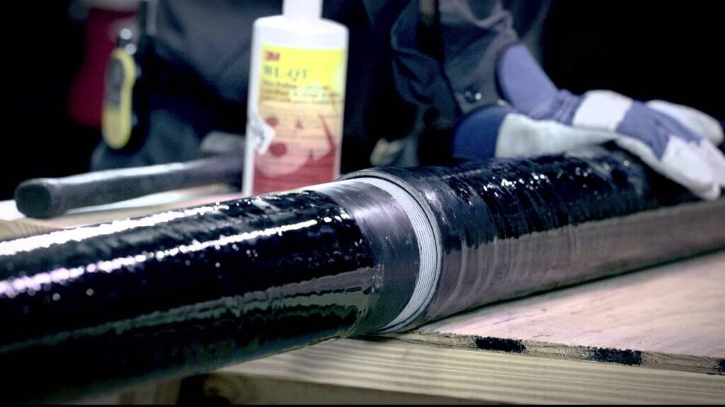
يتم ربط أنابيب RTRC باستخدام المواد اللاصقة أو الإيبوكسي المكون من جزأين المصمم لأنظمة أنابيب الألياف الزجاجية.
تحضير الأسطح: قم بتنظيف أطراف الأنابيب والتجهيزات الداخلية لإزالة الغبار والأوساخ والزيوت.
ضع المادة اللاصقة: استخدم الإيبوكسي الموصى به. ضعه بكمية وفيرة على كلا سطحي الوصل.
الانضمام والتعيين: أدخل الأنبوب في التركيبة ولفّه. ثبّته لفترة وجيزة حتى يبدأ بالالتصاق.
وقت المعالجة: اسمح بالمعالجة الكاملة وفقًا لإرشادات الشركة المصنعة قبل تطبيق الحمل أو الإجهاد.
تحتاج أنابيب RTRC إلى دعم مناسب، وخاصة في التطبيقات الأفقية:
- استخدم الأشرطة أو الشماعات أو المشابك المعتمدة كل 6 إلى 10 أقدام وفقًا لمتطلبات NEC.
- الوصلات التمددية: تتضمن وصلات التمدد في المسافات الطويلة أو المناطق ذات التقلبات في درجات الحرارة.
لا يتم عادةً ثني أنابيب RTRC في الموقع:
- استخدم المرفقين والانحناءات المصنعة في المصنع (على سبيل المثال، 90 درجة، 45 درجة)، والتي تم ربطها باستخدام مادة لاصقة.
- لا انحناء بالحرارة: يؤدي التسخين إلى الإضرار بسلامة هيكل RTRC.
بمجرد معالجة المادة اللاصقة، انتقل إلى تركيب الأسلاك:
- استخدم شريط السمك أو خيط السحب لتوجيه الأسلاك عبر القناة.
- استخدم مواد التشحيم على الجولات الطويلة أو المعقدة لتسهيل السحب.
- تأكد من أن التوصيل الأرضي والترابط متوافق مع NEC، حيث أن RTRC غير موصل.
قبل تنشيط النظام:
- قم بفحص جميع الوصلات اللاصقة للتأكد من الترابط الآمن.
- تأكد من أن جميع الدعامات موجودة في مكانها وعلى فترات زمنية صحيحة.
5. الخاتمة
| سمات | شركة آر إم سي | اي ام سي | فني الطوارئ الطبية | بولي فينيل كلوريد | مركز أبحاث ودراسات حقوق الإنسان |
|---|---|---|---|---|---|
| يكلف | أعلى تكلفة أولية | تكلفة معتدلة | أقل من RMC وIMC | أقل تكلفة أولية | تكلفة متوسطة إلى عالية |
| متانة | متينة للغاية، شديدة التحمل | متين، ولكنه أخف وزنًا من RMC | أقل متانة من RMC وIMC | متين، ولكن ليس قويًا مثل المعدن | متينة للغاية ومقاومة للصدمات |
| مقاومة التآكل | جيد مع الطلاءات | أفضل مع الطلاءات | عرضة للتآكل ما لم يتم طلائها | ممتاز ومقاوم طبيعيا | ممتاز ومقاوم للغاية |
| سهولة التثبيت | ثقيل، ويتطلب المزيد من العمل | معتدل، أخف من RMC | أسهل في التثبيت | سهل وخفيف الوزن ومرن | سهلة التركيب وخفيفة الوزن |
أهمية اختيار القناة المناسبة للبيئات المختلفة
بالنسبة للتطبيقات فوق الأرض، يجب إعطاء الأولوية للخيارات المقاومة للأشعة فوق البنفسجية لتحمل أشعة الشمس القاسية، بينما بالنسبة للتركيبات تحت الأرض، يجب التركيز على مقاومة الرطوبة والتآكل للحماية من العوامل البيئية.
المناطق المعرضة للرطوبة
في البيئات التي تكثر فيها الرطوبة - مثل الأقبية أو الحمامات أو المنشآت الخارجية - يعد اختيار القنوات المقاومة للماء أمرًا حيويًا.
تساعد الخيارات مثل أنابيب PVC أو الأنابيب المتخصصة المقاومة للرطوبة على منع التآكل، والذي يمكن أن يؤدي إلى أعطال كهربائية ومخاطر تتعلق بالسلامة.
بالإضافة إلى ذلك، غالبًا ما تلبي الأنابيب المقاومة للرطوبة معايير محددة للمواقع الرطبة، مما يضمن الامتثال للمعايير الكهربائية.
مخاطر التآكل
في البيئات الصناعية أو التجارية، قد تتعرض الأنابيب لمواد كيميائية مختلفة، بما في ذلك المذيبات أو الأحماض أو المواد الكاوية.
يساعد استخدام الأنابيب المصنوعة من مواد تقاوم التحلل الكيميائي - مثل أنواع معينة من الأنابيب المصنوعة من مادة PVC أو المعدن - في الحفاظ على سلامة الأسلاك.
لا يمنع هذا الاختيار تلف القناة نفسها فحسب، بل يحمي أيضًا البيئة المحيطة والموظفين من التعرض للخطر.
في المناطق الساحلية أو الأماكن ذات الرطوبة العالية، يعد اختيار القنوات المقاومة للتآكل أمرًا ضروريًا.
يمكن للخيارات مثل الأنابيب المصنوعة من الألياف الزجاجية أو الفولاذ المقاوم للصدأ أن تتحمل الظروف البيئية القاسية، مما يمنع التدهور المبكر ويضمن الموثوقية على المدى الطويل.
يعد هذا الاختيار مهمًا بشكل خاص بالنسبة للمنشآت الموجودة تحت الأرض أو المغمورة بالمياه، حيث يكون التعرض للرطوبة والأملاح أمرًا لا مفر منه.
درجات الحرارة القصوى
تتطلب المناطق التي تشهد درجات حرارة شديدة، سواء كانت حارة أو باردة، قنوات مصممة لتحمل مثل هذه الظروف.
على سبيل المثال، تضمن الأنابيب المصممة لمقاومة الحرارة العالية أو التجمد بقاء الأسلاك وظيفية دون المساس بالسلامة.
في درجات الحرارة الباردة الشديدة، قد تكون هناك حاجة إلى قنوات مرنة لمنع التشقق، بينما في درجات الحرارة المرتفعة، يمكن للمواد المقاومة للأشعة فوق البنفسجية أن تحمي من التعرض لأشعة الشمس.
ومن خلال دراسة هذه العوامل بعناية، يمكنك اتخاذ خيار مستنير يلبي احتياجات الأداء والمعايير التنظيمية، مما يساهم في نهاية المطاف في نجاح مشروعك.
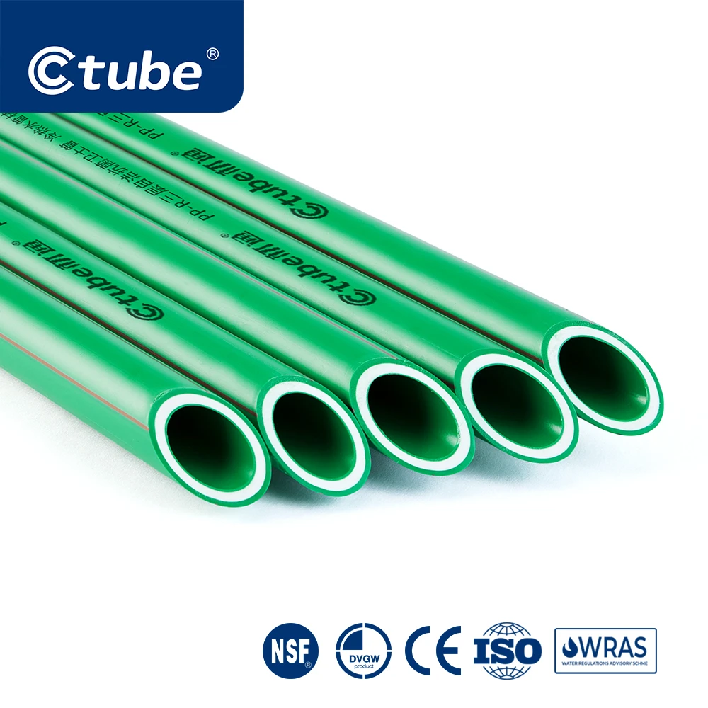
سي تيوب هي شركة رائدة في تصنيع حلول أنابيب PVC عالية الجودة، وتكرس جهودها لتقديم منتجات موثوقة ومتينة للتركيبات الكهربائية.
نحن شركة مقرها في الصين، متخصصون في إنتاج مجموعة واسعة من القنوات المصممة لتلبية الاحتياجات المتنوعة لمختلف الصناعات، مع ضمان الامتثال للمعايير الدولية.
تلتزم أنابيب PVC الصلبة الخاصة بنا بشهادات صارمة مثل UL 651 و AS/NZS 2053 و CSA، مما يضمن أداءً استثنائيًا ومتانة وسلامة في مختلف المناطق.
شكرًا لكم على القراءة! نأمل أن يكون هذا المنشور مفيدًا لمشروعكم. نتمنى لكم التوفيق في جميع أعمالكم، ولا تترددوا في التواصل معنا إذا كانت لديكم أي احتياجات أو استفسارات بخصوص مشاريعكم.
الأسئلة الشائعة
1. كيف يتم مقارنة الأنابيب الصلبة مع الأنابيب المرنة؟
يوفر الأنبوب الصلب مزيدًا من الحماية بسبب بنيته الصلبة، مما يجعله مثاليًا للبيئات ذات الضغط الميكانيكي الثقيل أو التعرض للرطوبة والمواد الكيميائية.
تعتبر الأنابيب المرنة أسهل في التركيب وتسمح بالحركة، مما يجعلها أكثر ملاءمة للمناطق التي تحتاج إلى المرونة.
2. كيف يتم تأمين الأنابيب الصلبة أثناء التثبيت؟
يتم تأمين الأنابيب الصلبة باستخدام أنواع مختلفة من أدوات التثبيت، مثل المشابك والأقواس والأشرطة، اعتمادًا على بيئة التثبيت (داخليًا أو خارجيًا أو تحت الأرض). تضمن هذه أدوات التثبيت بقاء الأنابيب ثابتة في مكانها وتحمي الأسلاك الموجودة بالداخل.
3. كيفية تحويل الزاوية مع قناة كهربائية صلبة؟
تلعب تجهيزات الأنابيب دورًا حاسمًا في ضمان الانعطافات السلسة لأنظمة الأنابيب الصلبة. تشمل التجهيزات الشائعة المرفقين والانحناءات الكاسحة، المصممة لإنشاء انعطافات بزاوية 90 درجة أو بزاوية مثل زوايا 45 درجة و22.5 درجة. تُستخدم أيضًا موصلات التي بشكل متكرر للسماح للأنابيب بالتفرع في اتجاهات مختلفة.
من بين الأنابيب الصلبة، تعد الأنابيب المعدنية الكهربائية (EMT) هي الأسهل في الثني. تعد الأدوات مثل زنبرك الأنابيب أو أداة ثني الأنابيب ضرورية لعمل ثنيات دقيقة، وضمان المحاذاة والتركيب المناسبين.