1. Introducción: comprensión de los conductos eléctricos rígidos
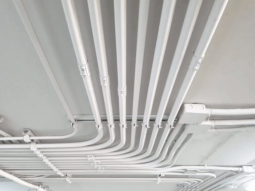
En el ámbito de los sistemas eléctricos, los conductos desempeñan un papel fundamental a la hora de garantizar la seguridad, la longevidad y la funcionalidad.
Los conductos eléctricos sirven como canales protectores a través de los cuales pasa el cableado eléctrico, protegiendo los cables de daños físicos, humedad, productos químicos y otros factores ambientales.
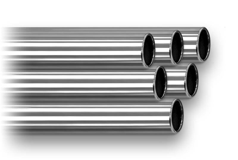
Entre los diversos tipos de conductos disponibles, el conducto eléctrico rígido destaca por su robustez e idoneidad tanto en aplicaciones industriales como residenciales.
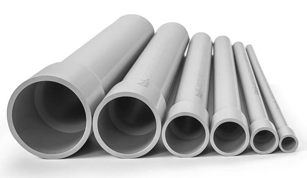
Los conductos eléctricos rígidos están disponibles en una variedad de formas, cada una diseñada para satisfacer necesidades específicas según el material y la aplicación. Los materiales principales utilizados para los conductos eléctricos rígidos incluyen PVC (cloruro de polivinilo), acero galvanizado, aluminio y RTRC (conducto de resina termoendurecible reforzada), entre otros. Cada material aporta ventajas únicas, lo que hace que los conductos rígidos sean versátiles en una variedad de entornos y requisitos de proyecto. Al final de esta publicación, tendrá una comprensión completa de qué es el conducto eléctrico rígido, por qué es un componente esencial en los sistemas eléctricos modernos y cómo incorporarlo en su próximo proyecto para maximizar la seguridad, la eficiencia y el cumplimiento.
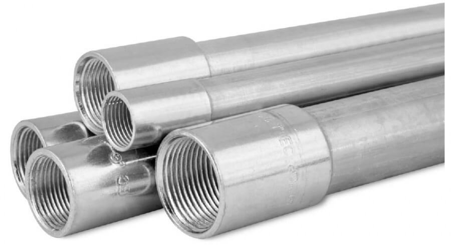
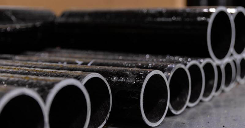
Conducto rígido de metal Incluye tipos como conductos metálicos rígidos (RMC), conductos metálicos intermedios (IMC) y tubos metálicos eléctricos (EMT), conocidos por su resistencia y durabilidad, lo que los hace adecuados para uso industrial y en exteriores.Conducto rígido de plástico, como el cloruro de polivinilo rígido (PVC), es liviano, resistente a la corrosión y se utiliza comúnmente en entornos donde la protección contra la humedad es esencial, como las instalaciones subterráneas.
Además, Conducto RTRC, fabricado con fibra de vidrio, ofrece un excelente aislamiento eléctrico, resistencia térmica y protección contra la corrosión, lo que lo convierte en una opción ideal para aplicaciones que requieren materiales no conductores y de alta resistencia.
En el siguiente artículo presentaremos los detalles de los conductos rígidos fabricados con diferentes materiales.
2. Tipos de conductos eléctricos rígidos: introducción detallada
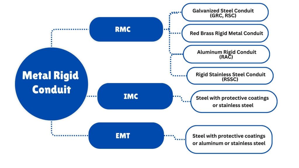
RMC está disponible en los siguientes materiales:
• Acero con recubrimientos protectores
• Aluminio
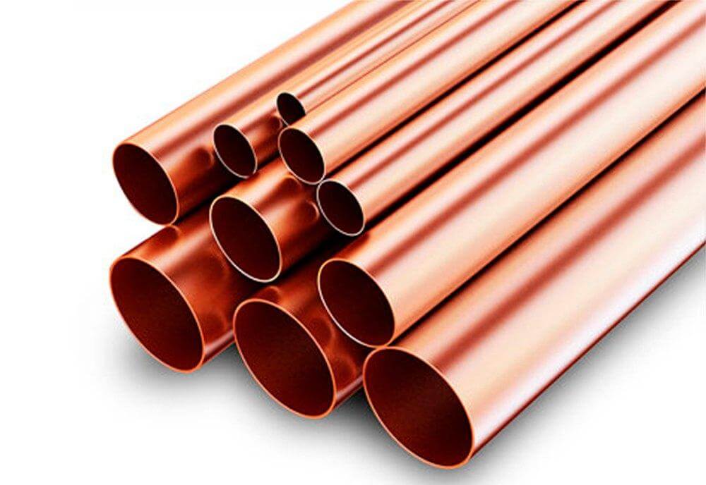
• Latón rojo
• Acero inoxidable
Material y estructura
Cada tubo utilizado para Conducto Rígido de Acero (RSC) deberá ser de acero, asegurándose que sea recto y presente una sección transversal circular.
| Designador métrico | Diámetro exterior (mm) | Tamaño del comercio | Diámetro externo, a (en) |
|---|---|---|---|
| 12b | 17.15 | 3/8b | 0.675 |
| 16 | 21.34 | 1/2 | 0.840 |
| 21 | 26.67 | 3/4 | 1.050 |
| 27 | 33.40 | 1 | 1.315 |
| 35 | 42.16 | 1-1/4 | 1.660 |
| 41 | 48.26 | 1-1/2 | 1.900 |
| 53 | 60.33 | 2 | 2.375 |
| 63 | 73.03 | 2-1/2 | 2.875 |
| 78 | 88.90 | 3 | 3.500 |
| 91 | 101.60 | 3-1/2 | 4.000 |
| 103 | 114.30 | 4 | 4.500 |
| 129 | 141.30 | 5 | 5.563 |
| 155 | 168.28 | 6 | 6.625 |
a Tolerancias: Tamaño comercial 12–41 (3/8–1-1/2) ± 0,38 mm (±0,015 pulg.). Tamaño comercial 53–155 (2–6) ± 1%.
b En Estados Unidos, se permite el tamaño comercial 12 (3/8) para aplicaciones especiales. En Canadá, no se permite el tamaño comercial 12 (3/8) según el Código Eléctrico Canadiense, Parte I.
Costuras soldadas
El proceso de soldadura de los tubos RMC debe cumplir criterios estrictos para garantizar la seguridad y la funcionalidad.
Las costuras soldadas no deben tener remates metálicos, bordes afilados o proyecciones que puedan interferir con el cableado interno o el proceso de instalación.
Se permite un ligero reborde a lo largo del interior de la costura, siempre que sea liso y no exceda los 0,38 mm (0,015 pulgadas) de altura para los tamaños comerciales 12 a 53 (3/8 pulgadas a 2 pulgadas) o 0,51 mm (0,020 pulgadas) para los tamaños comerciales 63 a 155 (2 ½ pulgadas a 6 pulgadas).
Requisitos de longitud y peso estándar
La longitud estándar de los conductos rectos revestidos de zinc o de los tubos roscados desnudos que se revestirán con un material alternativo resistente a la corrosión, incluido un acoplamiento, debe seguir las especificaciones detalladas en la Tabla siguiente.
Estas tablas describen las dimensiones y pesos de los conductos que cumplen con las normas dadas.
| Designador métrico | Longitud del conducto rectoa (milímetros) |
Peso mínimo aceptable de 10 tramos de conducto con diez acoplamientos (kg) Conducto recubierto de zinc terminadob |
Peso mínimo aceptable de 10 tramos de conducto con diez acoplamientos (kg) Tubo roscado desnudoc |
Tamaño del comercio | Longitud del conducto recto Pies y pulgadasa ±1/4 |
Peso mínimo aceptable de 10 tramos de conducto con diez acoplamientos (libras) Conducto recubierto de zinc terminadob |
Peso mínimo aceptable de 10 tramos de conducto con diez acoplamientos (libras) Tubo roscado desnudoc |
|---|---|---|---|---|---|---|---|
| 12d | 3035 | 23.4 | 22.6 | 3/8 | 9′–11 1/2″ | 51.5 | 48.6 |
| 16 | 3030 | 35.8 | 34.4 | 1/2 | 9′–11″ | 78.9 | 75.8 |
| 21 | 3030 | 47.6 | 45.5 | 3/4 | 9′–11″ | 104.9 | 100.3 |
| 27 | 3030 | 69.4 | 65.8 | 1 | 9′–11″ | 153.0 | 145.1 |
| 35 | 3025 | 91.2 | 87.8 | 1-1/4 | 9′–11″ | 201.0 | 193.5 |
| 41 | 3025 | 112.9 | 109.4 | 1-1/2 | 9′–11″ | 249.0 | 241.2 |
| 53 | 3035 | 150.4 | 144.3 | 2 | 9′–11 1/2″ | 331.6 | 318.1 |
| 63 | 3010 | 209.6 | 203.4 | 2-1/2 | 9′–10 1/4″ | 462.0 | 448.4 |
| 78 | 3010 | 239.0 | 233.4 | 3 | 9′–10 1/4″ | 527.0 | 514.8 |
| 91 | 3010 | 274.1 | 268.4 | 3-1/2 | 9′–10 1/4″ | 604.4 | 591.5 |
| 103 | 2995 | 312.0 | 305.3 | 4 | 9′–10″ | 687.6 | 672.9 |
| 129 | 2995 | 591.7 | 578.6 | 5 | 9′–10″ | 1304.9 | 1275.6 |
| 155 | 2995 | 797.1 | 781.4 | 6 | 9′–10″ | 1757.0 | 1722.7 |
a Las longitudes indicadas están diseñadas para producir una longitud de conducto de 3,05 m (10 pies) cuando se conecta un acoplamiento de conducto con toma recta.
b Este conducto está protegido con un revestimiento de zinc o a base de zinc que consiste principalmente en zinc.
c Este conducto está diseñado para protegerse con un revestimiento alternativo resistente a la corrosión.
d En Estados Unidos, se permite el tamaño comercial 12 (3/8) para aplicaciones especiales. En Canadá, no se permite el tamaño comercial 12 (3/8) según el Código Eléctrico Canadiense, Parte I.
Requisitos de la prueba
Prueba de tubos de acero rígido
El proceso de prueba de tubos implica doblar una muestra del tamaño comercial más pequeño disponible en un cuarto de círculo alrededor de un mandril, primero a temperatura ambiente y luego después de acondicionarlo a 0 °C (32 °F) durante 60 minutos.
El tubo no debe agrietarse ni romperse la soldadura. Si el tubo tiene un revestimiento no metálico y está clasificado para temperaturas inferiores a 0 °C, la prueba se realiza a esa temperatura inferior.
| Recubrimientos | Pruebas | Cláusula # |
|---|---|---|
| Zinc | Prueba de flexión Curva fría Prueba de recubrimiento de zinc |
6.2.1.1 6.2.1.3 6.2.2 |
| Resistente a la corrosión alternativa | Prueba de flexión Curva fría Luz ultravioleta y agua Niebla salina (niebla) CO₂–SO₂–Aire húmedo De tensión Adhesión Propagación de la llama |
6.2.1.1 6.2.1.3 6.2.4.3 6.2.4.5 6.2.4.6 6.2.4.8 6.2.4.9 6.2.4.11 |
| No metálicos resistentes a la corrosión alternativos (además de los anteriores) | Ensamblaje, flexión, resistencia, tracción y corriente de falla Continuidad eléctrica Identificación de compuestos Impacto de frío |
5.3.3.2 5.3.5.2 6.2.1.5 6.2.1.0 |
| Orgánico | Prueba de flexión Curva fría Identificación de compuestos Elasticidad Prueba de aire cálido y húmedo |
6.2.1.1 6.2.1.3 6.2.1.5 6.2.3.5 6.2.3.2 |
| Recubrimientos suplementarios | Efectos perjudiciales para el recubrimiento primario Ajuste de acoplamientos Continuidad eléctrica Propagación de la llama |
5.3.5.2 5.3.5.2 5.3.5.2 6.2.4.11 |
| Tratamiento de superficies | N/A si el espesor es inferior a 0,038 mm (0,00015 pulgadas) | 5.3.6.1 |
Prueba de revestimiento de conductos de acero rígidos
En la siguiente tabla se describen diferentes pruebas para varios tipos de recubrimientos aplicados a tubos, incluidos recubrimientos de zinc, alternativos resistentes a la corrosión, no metálicos, orgánicos y complementarios.
Estas pruebas evalúan el rendimiento del recubrimiento en diferentes condiciones, como flexión, exposición a la luz ultravioleta, niebla salina, temperaturas frías y continuidad eléctrica.
Canalización roscada de acero inoxidable con sección transversal circular diseñada para la protección física y el enrutamiento de conductores de cables y para uso como conductor de conexión a tierra de equipos cuando se instala utilizando accesorios adecuados.
Conducto metálico rígido eléctrico de latón rojo (ERMC-RB)
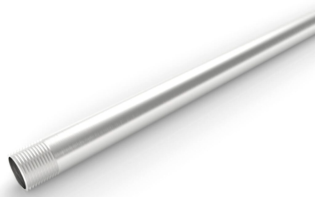
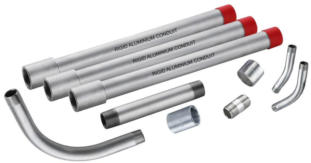
Conducto metálico rígido eléctrico de aluminio (ERMC-A)
| Tamaño del comercio | Diámetro interior nominal (pulg.) | Diámetro exterior (pulg.) | Espesor de la pared (pulg.) | Longitud sin acoplamiento (pies y pulgadas) | Peso mínimo (10 piezas con acoplamientos) (lb) |
|---|---|---|---|---|---|
| 1/2 | 0.632 | 0.840 | 0.104 | 9'11-1/4″ | 27.4 |
| 3/4 | 0.836 | 1.050 | 0.107 | 9'11-1/4″ | 36.4 |
| 1 | 1.063 | 1.315 | 0.126 | 9'11’ | 50.7 |
| 1-1/4 | 1.394 | 1.660 | 0.138 | 9'11’ | 66.2 |
| 1-1/2 | 1.624 | 1.900 | 0.138 | 9'11’ | 86.2 |
| 2 | 2.067 | 2.375 | 0.154 | 9'10-1/2″ | 125.0 |
| 2-1/2 | 2.489 | 2.875 | 0.193 | 9'10-1/2″ | 182.5 |
| 3 | 3.068 | 3.500 | 0.225 | 9'10-1/4″ | 236.8 |
| 3-1/2 | 3.570 | 4.000 | 0.245 | 9'10-1/4″ | 358.7 |
| 4 | 4.032 | 4.500 | 0.265 | 9'10’ | 454.9 |
| 5 | 5.073 | 5.563 | 0.245 | 9'10’ | 454.9 |
| 6 | 6.093 | 6.625 | 0.266 | 9'10’ | 604.4 |
| Tamaño del comercio | Diámetro exterior (pulg.) Máximo |
Diámetro exterior (pulg.) Mínimo |
Espesor de la pared (pulg.) Máximo |
Espesor de la pared (pulg.) Mínimo |
Diámetro interior nominal (pulg.) | Longitud sin acoplamiento (pies y pulgadas) |
|---|---|---|---|---|---|---|
| 1/2 | 0.820 | 0.810 | 0.085 | 0.070 | 0.659 | 9'11-1/4″ |
| 3/4 | 1.034 | 1.024 | 0.090 | 0.075 | 0.863 | 9'11-1/4″ |
| 1 | 1.295 | 1.285 | 0.100 | 0.085 | 1.063 | 9'11’ |
| 1-1/4 | 1.645 | 1.630 | 0.105 | 0.085 | 1.448 | 9'11’ |
| 1-1/2 | 1.890 | 1.875 | 0.115 | 0.090 | 1.683 | 9'11’ |
| 2 | 2.367 | 2.352 | 0.115 | 0.095 | 2.150 | 9'11’ |
| 2-1/2 | 2.867 | 2.847 | 0.160 | 0.140 | 2.575 | 9'10-1/2″ |
| 3 | 3.486 | 3.466 | 0.160 | 0.140 | 3.176 | 9'10-1/2″ |
| 3-1/2 | 3.981 | 3.961 | 0.160 | 0.140 | 4.161 | 9'10-1/4″ |
| 4 | 4.476 | 4.456 | 0.160 | 0.140 | 4.166 | 9'10-1/4″ |
• Acero con recubrimientos protectores
• Aluminio
La superficie interior deberá estar recubierta con zinc o con un revestimiento orgánico. Este revestimiento interior debe mantener una superficie lisa y continua, con variaciones menores debidas a un flujo de revestimiento irregular que se considere aceptable.
| Tamaño del comercio | Designador métrico | Longitud máxima (pies) | Longitud máxima (m) |
|---|---|---|---|
| 1/2 – 3/4 | 16 – 21 | 10′ 1/4″ | 3.05 |
| 1 – 2 | 27 – 53 | 15′ 1/4″ | 4.58 |
| 2-1/2 – 4 | 63 – 103 | 20′ 1/4″ | 6.10 |
Artículo 342 Conducto Metálico Intermedio mencionadot IMC está disponible en los siguientes materiales:
- Acero con recubrimientos protectores
- Aluminio
| Tamaño del comercio | Designador métrico | Diámetro externo (pulg.) | Diámetro interno (pulg.) | Espesor de la pared (pulg.) | Peso mínimo del aluminio (lb/ft) | Peso mínimo de acero inoxidable (lb/ft) |
|---|---|---|---|---|---|---|
| 1/2 | 16 | 0,705 ±0,005 | 0.622 | 0.042 | 0.099 | 0.300 |
| 3/4 | 21 | 0,922 ±0,005 | 0.824 | 0.049 | 0.159 | 0.500 |
| 1 | 27 | 1,163 ±0,005 | 1.049 | 0.057 | 0.221 | 0.700 |
| 1-1/4 | 35 | 1,510 ±0,005 | 1.380 | 0.065 | 0.381 | 1.100 |
| 1-1/2 | 41 | 1,740 ±0,005 | 1.610 | 0.065 | 0.430 | 1.200 |
| 2 | 53 | 2,197 ±0,005 | 2.067 | 0.065 | 0.484 | 1.380 |
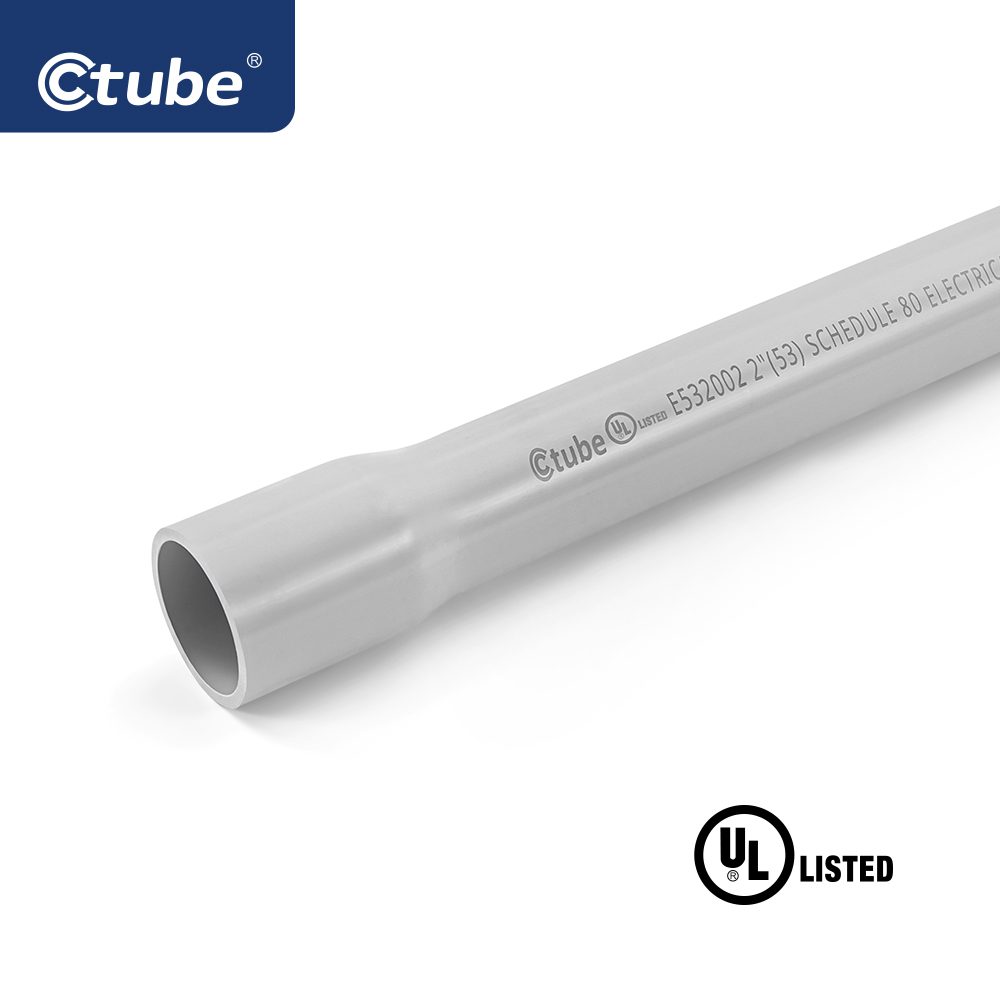
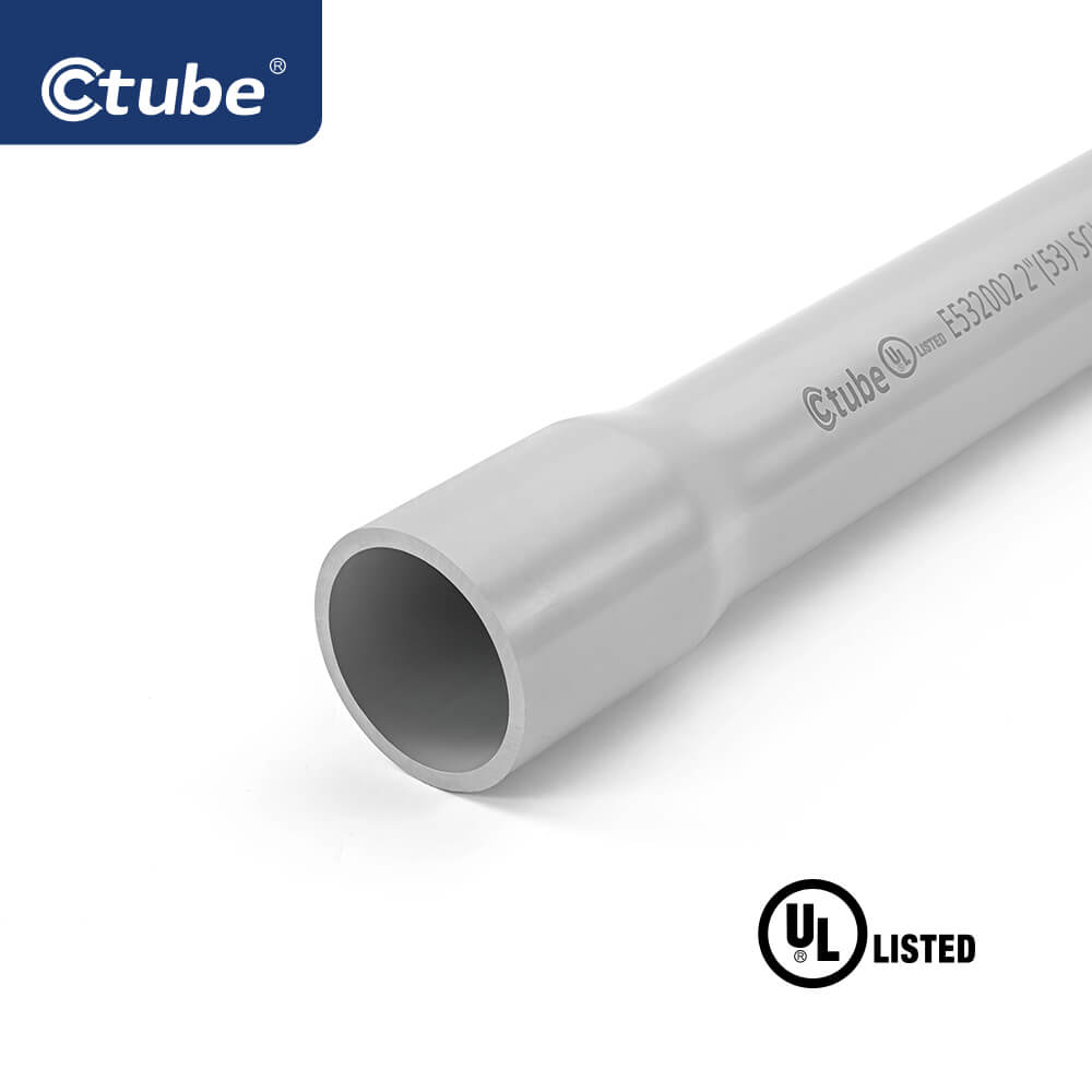
Prueba de conductos de PVC rígidos
Los conductos cédula 40 y cédula 80 tienen diámetros exteriores definidos y espesores de pared mínimos según el tamaño comercial. Esto garantiza la integridad estructural en diversas aplicaciones.
Las muestras de conductos se prueban según la norma ASTM D 638. Las muestras envejecidas deben conservar 95% de la resistencia a la tracción de las muestras no envejecidas. La resistencia mínima es de 5000 psi para conductos de cédula 40/80 y de 4000 psi para conductos de tipo A y EB.
Se prueban diez muestras de conducto de 6 pulgadas con pesas de caída. No más de tres pueden agrietarse o romperse más de 1/32 de pulgada. Se utilizan diferentes pesas: 20 lb para SCH 40, Tipo A y EB; 75 lb para SCH 80.
El conducto debe autoextinguirse en un plazo de 5 segundos tras la exposición a la llama y no encender los materiales cercanos. La prueba se asemeja a la clasificación UL 94 V-0, que exige alta resistencia a la llama y ausencia de goteos de llama.
Los conductos no deben deformarse ni separarse bajo presión entre las placas de acero. Las muestras aplanadas deben mantener al menos 70% de su diámetro interior original.
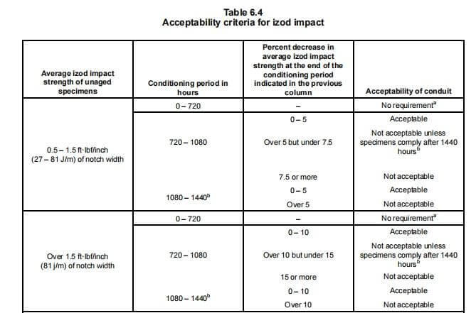
La resistencia al aplastamiento mide la capacidad de un material para soportar fuerzas de compresión constantes (p. ej., la presión del suelo). La resistencia al impacto mide la respuesta a impactos o caídas repentinas. Ambas son cruciales en diferentes condiciones de campo.
Para las cédulas 40 y 80, las pruebas de exposición a la luz solar se basan en la resistencia al impacto Izod (≥0,5 ft-lbf/pulgada). Las muestras se prueban durante periodos de 720 a 1440 horas según los métodos ASTM D 256 para garantizar su durabilidad en condiciones de luz ultravioleta.
Los tipos se definen por sistema de diámetro y espesor de pared:
- IDENTIFICACIÓN: Diámetro interior
- IPS: Tamaño de la tubería de hierro (diámetro exterior)
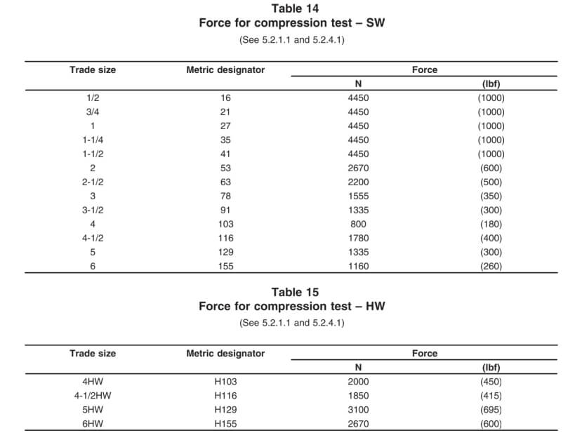
- Espesor de la pared: SW (Estándar), MW (Medio), HW (Pesado), XW (Extra Pesado)

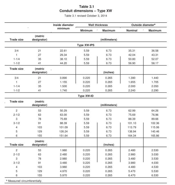
Aplicaciones:
- Sobre el suelo: UL 2515
- Subterráneo: UL 2420
Cada muestra se prueba para determinar la duración posterior a la aplicación de la llama: la aplicación de la llama no debe exceder los 30 segundos después de las primeras cuatro aplicaciones, ni los 60 segundos después de la quinta.
El opcional FT4 La prueba de llama es una de las más rigurosas, requerida en ciertas construcciones canadienses de materiales no combustibles. Implica la exposición a... 70.000 BTU/hora llama durante 20 minutos.
Criterios de aprobación: La longitud carbonizada no debe exceder 1,5 m (5 pies) desde la parte inferior del quemador (CSA C22.2 No.38).
Pruebas de calificación para conductos de resina termoendurecible reforzada (RTRC)
3. Análisis de los requisitos de profundidad de enterramiento para conductos eléctricos rígidos
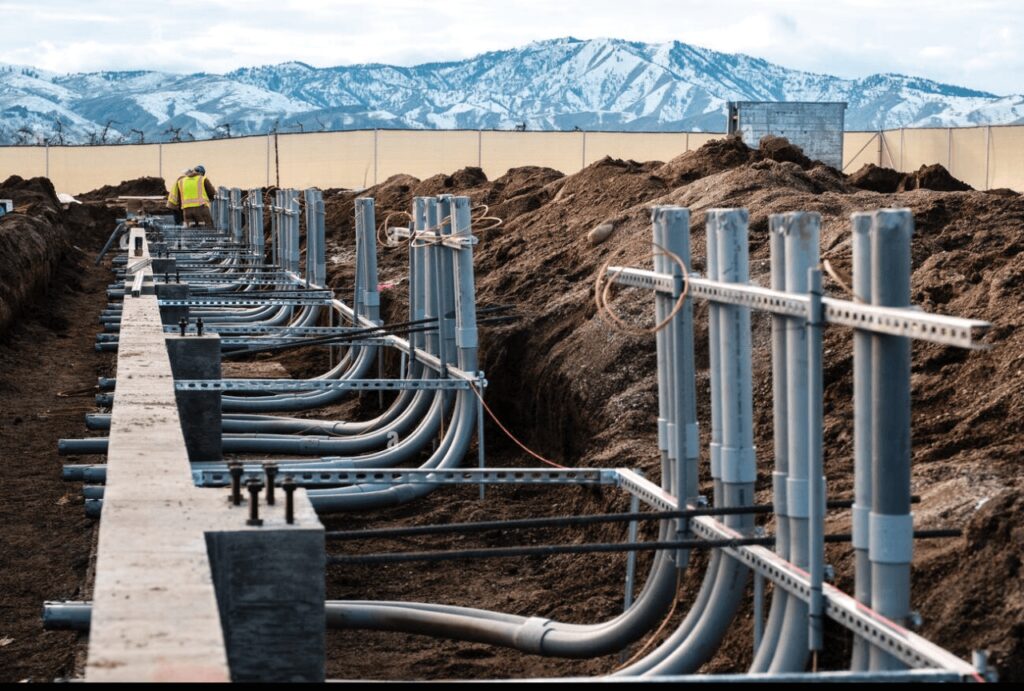
En el ámbito de las instalaciones eléctricas, la profundidad de enterramiento adecuada de los conductos es fundamental para garantizar la seguridad, el cumplimiento normativo y la durabilidad. Los conductos eléctricos rígidos, incluidos los conductos metálicos rígidos (RMC), los conductos no metálicos como el PVC y los conductos de fibra de vidrio, tienen requisitos de profundidad de enterramiento específicos dictados tanto por el Código Eléctrico Nacional (NEC) como por los códigos de construcción locales.
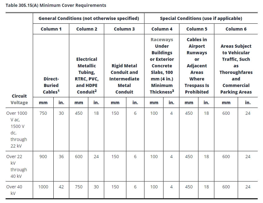
Notas:
1. Cubrir Se definirá como la distancia más corta en milímetros (pulgadas) medida entre un punto en la superficie superior de cualquier conductor, cable, conducto u otra canalización directamente enterrado y la superficie superior de una cubierta terminada, de hormigón o similar.
2. Se permitirán profundidades menores cuando los cables y conductores se eleven para realizar terminaciones o empalmes o cuando se requiera acceso de otro modo.
3. Cuando la roca sólida impida cumplir con las profundidades de recubrimiento especificadas en esta tabla, el cableado se instalará en una canalización metálica o no metálica, permitida para enterramiento directo. Las canalizaciones deberán estar cubiertas por un mínimo de 50 mm (2 pulg.) de hormigón que llegue hasta la roca.
4. En establecimientos industriales, donde las condiciones de mantenimiento y supervisión garanticen que personal calificado dará servicio a la instalación, se permitirá que los requisitos mínimos de cobertura para conductos metálicos distintos de los rígidos y los intermedios se reduzcan en 150 mm (6 pulg.) por cada 50 mm (2 pulg.) de hormigón o equivalente colocado completamente dentro de la zanja sobre la instalación subterránea.
5. Cables enterrados directamente: Los cables enterrados directamente bajo tierra que no estén revestidos ni protegidos por hormigón y que estén enterrados a 750 mm (30 pulgadas) o más por debajo del nivel del suelo deberán tener su ubicación identificada mediante una cinta de advertencia que se coloca en la zanja al menos 300 mm (12 pulgadas) por encima de los cables.
6. Tuberías metálicas eléctricas, conductos RTRC, PVC y HDPE: Estos pueden estar certificados por una agencia de pruebas cualificada como aptos para enterramiento directo sin encapsulamiento. Todos los demás sistemas no metálicos requerirán 50 mm (2 pulg.) de hormigón o equivalente por encima del conducto, además de la profundidad de la mesa.
7. Canalizaciones bajo edificios o losas de hormigón exteriores (espesor mínimo de 100 mm/4 pulg.): La losa deberá extenderse un mínimo de 150 mm (6 pulgadas) más allá de la instalación subterránea, y se deberá colocar una cinta de advertencia u otro medio efectivo adecuado para las condiciones sobre la instalación subterránea.
8. Otros cables no blindados no cubiertos en 305.15(A)(1) o (A)(2) se deberán instalar en conductos metálicos rígidos, conductos metálicos intermedios o conductos no metálicos rígidos revestidos con no menos de 75 mm (3 pulg.) de hormigón.
9. Conductores que emergen del suelo: Estos deberán estar encerrados en canalizaciones homologadas. Las canalizaciones instaladas en los postes deberán ser de conducto metálico rígido, conducto metálico intermedio, RTRC-XW, conducto de PVC cédula 80 o equivalente, extendiéndose desde la profundidad mínima de cobertura especificada en la Tabla 305.15(A) hasta un punto a 2,5 m (8 pies) sobre el nivel del suelo.
Los factores ambientales influyen significativamente en la profundidad de enterramiento de los conductos. Las condiciones del suelo, como la estabilidad y el contenido de humedad, pueden determinar la profundidad a la que se debe instalar un conducto para garantizar que permanezca seguro a lo largo del tiempo. Por ejemplo, en suelos rocosos o inestables, puede ser necesario un enterramiento más profundo para evitar daños por el movimiento del suelo.
Las cargas de tráfico también juegan un papel fundamental, en particular en áreas donde los conductos se instalan debajo de carreteras o estacionamientos. En estos casos, suele ser necesario enterrarlos a mayor profundidad para protegerlos del peso y la vibración de los vehículos y el equipo pesado.
4. Pautas de instalación para diferentes tipos de conductos rígidos
Antes de comenzar, reúna las siguientes herramientas y materiales:
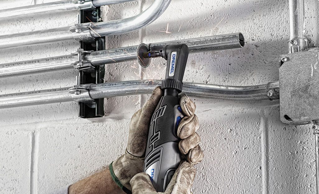
• Herramientas de corte: Sierra para metales o cortadora de rollos (si es necesario cortar).
• Escariador: Para eliminar rebabas dentro del conducto después del corte.
• Dobladora de conductos: Para realizar curvas precisas.
• Llaves: De tamaño adecuado.
• Compuesto sellador de roscas o pintura resistente a la corrosión: Para proteger los hilos si es necesario.
Confirme también que tiene todos los accesorios, acoplamientos y conectores necesarios para garantizar una conexión a tierra adecuada.
• Medir y cortar: Mida la longitud necesaria y córtela limpiamente con una sierra.
• Resma: Retire las rebabas del interior del conducto para evitar dañar el cable.
• Enhebrado: Si es necesario, utilice una matriz estándar de ¾ de pulgada por pie (NPT) para roscar. Las roscas deben ser lisas y limpias.
Para conductos pre-roscados, omita la rosca pero proteja las roscas expuestas o dañadas.
• Apretar a mano y terminar con llave: Comience a apretar con la mano, luego apriete con la llave, generalmente una vuelta completa más allá del apriete manual.
• Evite apretar demasiado: Una fuerza excesiva puede dañar las roscas y el revestimiento. No utilice extensiones de llave.
• Para conexiones sin rosca, empuje el conducto completamente dentro del conector y asegúrelo con el torque adecuado.
• Doblado a mano: Los tamaños pequeños (de ½ a 1 pulgada) se pueden doblar con una dobladora manual; los tamaños más grandes requieren dobladoras mecánicas o eléctricas.
• Precisión: Marcar las curvas; evitar exceder los 90° entre los puntos de tracción.
• Evite las torceduras: Evite que se aplanen o se doblen, lo que reduce el espacio y complica el tendido del cable.
• Para conductos pre-roscados, evite dañar las roscas durante el doblado.
• Utilice correas, perchas o abrazaderas para asegurar los conductos a las paredes, techos o miembros estructurales.
• Para tramos verticales, asegure el conducto en el extremo superior para evitar que se combe.
• Para conductos que pasan de concreto a tierra o bajo tierra, aplique revestimientos, envolturas o conductos recubiertos de PVC aprobados para mayor protección.
• Inspeccione los recubrimientos aplicados de fábrica para detectar daños durante la instalación.
• Aplique compuestos resistentes a la corrosión, pintura rica en zinc o cinta resistente a la corrosión según sea necesario.
• Proteja las roscas cortadas en campo con recubrimientos conductores de electricidad y resistentes a la corrosión.
• Realizar pruebas de continuidad para confirmar la continuidad eléctrica y la conexión a tierra.
• Inspeccione todas las conexiones de conductos para verificar que estén bien ajustadas y que los soportes estén seguros.
• Verificar que los recubrimientos protectores permanezcan intactos y que se apliquen protecciones adicionales según sea necesario.
Antes de comenzar, reúna las herramientas y los materiales necesarios para una instalación exitosa del conducto de PVC:
Conducto de PVC: El diámetro y longitud adecuados para su proyecto.
Accesorios de PVC: Acoplamientos, codos, cajas de conexiones y otros componentes.
Cemento e Imprimación para PVC: Para asegurar juntas y accesorios.
Cortador de conductos o sierra para metales: para cortar el conducto a la longitud requerida.
Herramienta desbarbadora: para alisar los bordes cortados del conducto.
Cinta métrica: Para mediciones precisas.
Nivel: Para garantizar una alineación adecuada.
Cuerda de tracción o cinta de pesca: para tirar de los cables a través del conducto después de la instalación.
Antes de comenzar la instalación, planifique cuidadosamente la ruta del conducto de PVC. Esto incluye medir la distancia entre los puntos por donde pasará el conducto y señalar dónde se necesitarán curvas, accesorios y uniones.
Medir y marcar: utilice una cinta métrica para determinar la longitud del conducto de PVC necesario para cada sección y marque dónde se realizarán los cortes.
Tenga en cuenta la expansión y la contracción: los conductos de PVC se expanden y contraen con los cambios de temperatura, por lo que deberá dejar algo de espacio para el movimiento o instalar accesorios de expansión en tramos largos.
Cortar conductos de PVC es mucho más fácil que cortar conductos de metal, pero aun así es importante realizar cortes limpios y precisos para garantizar una instalación sin problemas.
Corte el conducto: utilice un cortador de conductos de PVC o una sierra para metales de dientes finos para cortar el conducto según las longitudes medidas. Asegúrese de que los cortes sean rectos y limpios.
Desbarbe los bordes: después de cortar, use una herramienta desbarbadora o un cúter para eliminar los bordes ásperos o las rebabas del interior y el exterior del conducto. Este paso es fundamental para evitar dañar los cables cuando se pasan por el conducto.
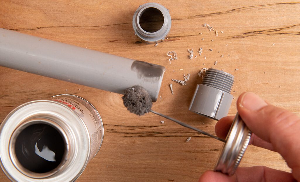
A diferencia de los conductos metálicos, en los que se utilizan roscas o tornillos de fijación, las secciones de conductos de PVC se unen mediante un proceso denominado soldadura con disolvente. Esto implica el uso de una imprimación y cemento para PVC para unir el conducto y los accesorios.
Aplicar imprimación: primero, limpie los extremos del conducto y el interior de los accesorios con una imprimación para PVC. La imprimación ablanda el material y lo prepara para el proceso de unión.
Aplicar cemento para PVC: Inmediatamente después de aplicar la imprimación, cubra las mismas áreas con cemento para PVC. Asegúrese de trabajar rápidamente, ya que el cemento se seca rápidamente.
Unir el conducto y los accesorios: Empujar el conducto dentro del accesorio, girándolo ligeramente para asegurar que el cemento se extienda de manera uniforme. Mantener las piezas juntas durante unos segundos para asegurar una unión fuerte.
Limpie el exceso de cemento: elimine el exceso de cemento que se haya derramado durante el proceso de conexión. Deje que la unión se endurezca según las instrucciones del fabricante antes de seguir manipulándola.
Este proceso de soldadura con solvente crea un sello hermético, lo que hace que el PVC sea ideal para instalaciones exteriores y subterráneas donde la resistencia a la humedad es fundamental.
Doblar conductos de PVC es diferente a doblar conductos de metal. El PVC se puede doblar mediante calor para crear curvas suaves y personalizadas sin necesidad de codos prefabricados en algunas situaciones.
Calentar el conducto de PVC: utilice una pistola de calor o un calentador para doblar PVC para calentar la sección del conducto donde se necesita doblar. Asegúrese de aplicar calor de manera uniforme para evitar deformar el conducto.
Haz la curva: una vez que el conducto esté maleable, dóblalo lentamente hasta obtener el ángulo deseado. Mantenlo en su lugar hasta que se enfríe y conserve la forma.
Utilice codos prefabricados: para la mayoría de las instalaciones, es más fácil utilizar codos de PVC de 90 o 45 grados fabricados en fábrica, que se pegan en su lugar utilizando el mismo proceso de soldadura con solvente.
Dado que el PVC es más flexible y liviano que los conductos de metal, requiere un soporte adecuado para evitar que se combe o se mueva con el tiempo.
Instalación de correas o abrazaderas para conductos: Sujete el conducto de PVC a intervalos regulares sujetándolo con correas o abrazaderas. Siga las pautas del NEC, que recomiendan sujetar el PVC cada 3 a 6 pies, según el diámetro del conducto.
Permitir la expansión: los conductos de PVC se expanden y contraen con los cambios de temperatura. En tramos más largos, instale accesorios de expansión para permitir el movimiento sin forzar las juntas. Los accesorios de expansión son cruciales para instalaciones al aire libre o expuestas al sol donde las fluctuaciones de temperatura son significativas.
Una vez instalado el conducto y curadas las juntas de cemento, puedes pasar los cables a través del conducto.
Use una cinta pescadora o una cuerda de tracción: pase la cinta pescadora o la cuerda de tracción a través del conducto y luego fije los cables de forma segura a la cinta.
Tire de los cables: tire lentamente de los cables a través del conducto, asegurándose de que no se enganchen ni se dañen en los bordes ásperos.
Lubricar si es necesario: si el conducto es largo o tiene varias curvas, utilice un lubricante para tendido de cables para reducir la fricción y facilitar el proceso.
Una vez que se hayan tirado los cables y el sistema esté configurado, realice una inspección final para asegurarse de que todo esté instalado de forma correcta y segura.
Verifique las conexiones: asegúrese de que todas las uniones soldadas con solvente estén sólidas y que ningún accesorio se haya aflojado.
Verificar los soportes: Confirme que todas las correas y abrazaderas de los conductos estén espaciadas correctamente y seguras.
Para una instalación exitosa del conducto RTRC, reúna las siguientes herramientas y materiales:
- Conducto RTRC: Diámetro y longitudes de conductos adecuados.
- Accesorios RTRC: Acoplamientos, codos y otros componentes necesarios.
- Epoxi o adhesivo de dos componentes: Para unir secciones de conductos y accesorios.
- Sierra para metales o sierra de dientes finos: Para cortar el conducto a medida.
- Herramienta de desbarbado o papel de lija: Para suavizar los bordes cortados.
- Cinta métrica y nivel: Para mediciones y alineación precisas.
- Tirar de la cuerda o cinta de pescado: Para pasar los cables a través del conducto después de la instalación.
- Pistola de calor: Para componentes termorretráctiles si es necesario.
Al igual que con cualquier sistema de conductos, comience por planificar la ruta y el diseño de la instalación del RTRC. Identifique los puntos en los que los conductos cambiarán de dirección, dónde se necesitarán accesorios y dónde se deben colocar los puntos de acceso o las cajas de conexiones.
Medir y marcar: Utilice una cinta métrica para determinar con precisión las longitudes de conducto necesarias y marcar dónde será necesario realizar los cortes.
Cortar el conducto RTRC es similar a cortar PVC, pero la composición del material requiere una manipulación cuidadosa para evitar dañar la fibra.
Cortar el conducto: Utilice una sierra para metales, una sierra de sable o cualquier sierra de dientes finos para cortar el conducto a la longitud deseada. Asegúrese de que el corte sea recto para facilitar la unión.
Desbarbar los bordes: Después de cortar, alise los bordes interiores y exteriores con una herramienta desbarbadora o papel de lija. Esto evita dañar el aislamiento del cable.
Control de polvo: Al cortar RTRC, utilice EPP como guantes, protección para los ojos y una máscara antipolvo o un respirador para controlar el polvo de fibra de vidrio.
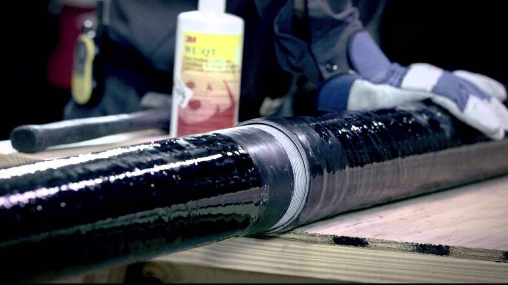
El conducto RTRC se une mediante adhesivos o un epoxi de dos partes diseñado para sistemas de conductos de fibra de vidrio.
Preparar las superficies: Limpie los extremos de los conductos y los interiores de los accesorios para eliminar el polvo, la suciedad y el aceite.
Aplicar el adhesivo: Utilice el epoxi recomendado. Aplique generosamente sobre ambas superficies a unir.
Unir y configurar: Inserte y gire el conducto en el conector. Sujételo brevemente hasta que comience el fraguado.
Tiempo de curado: Deje curar completamente según las pautas del fabricante antes de aplicar carga o tensión.
El conducto RTRC necesita un soporte adecuado, especialmente en aplicaciones horizontales:
- Utilice correas, perchas o abrazaderas aprobadas cada 6 a 10 pies según los requisitos del NEC.
- Juntas de Expansión: Incluya accesorios de expansión en recorridos largos o áreas con oscilaciones de temperatura.
El doblado de conductos RTRC normalmente no se realiza en el sitio:
- Utilice codos y curvas fabricados en fábrica (por ejemplo, 90°, 45°), unidos con adhesivo.
- Sin doblado por calor: El calentamiento daña la integridad estructural del RTRC.
Una vez curado el adhesivo, proceda a la instalación del cable:
- Utilice cinta de pescado o una cuerda para guiar los cables a través del conducto.
- Aplique lubricante en recorridos largos o complejos para facilitar el tirón.
- Asegúrese de que la conexión a tierra y la unión cumplan con las normas NEC, ya que el RTRC no es conductor.
Antes de energizar el sistema:
- Inspeccione todas las uniones adhesivas para confirmar que la unión sea segura.
- Verifique que todos los soportes estén en su lugar y en los intervalos correctos.
5. Conclusión
| Características | CMR | CMI | Técnico en emergencias médicas | CLORURO DE POLIVINILO | RTC-RTC |
|---|---|---|---|---|---|
| Costo | Costo inicial más alto | Costo moderado | Inferior a RMC e IMC | Costo inicial más bajo | Costo moderado a alto |
| Durabilidad | Muy duradero y resistente. | Durable, pero más ligero que el RMC | Menos duradero que RMC e IMC | Durable, pero no tan fuerte como el metal. | Muy duradero, resistente al impacto. |
| Resistencia a la corrosión | Bueno con recubrimientos | Mejor con recubrimientos | Propenso a la corrosión a menos que esté recubierto | Excelente, naturalmente resistente. | Excelente, muy resistente. |
| Facilidad de instalación | Pesado, requiere más mano de obra. | Moderado, más ligero que RMC | Más fácil de instalar | Fácil, ligero y flexible. | Fácil de instalar, ligero. |
Importancia de seleccionar el conducto adecuado para diferentes entornos
Para aplicaciones sobre el suelo, priorice las opciones con resistencia a los rayos UV para soportar la luz solar intensa, mientras que para instalaciones subterráneas, concéntrese en la resistencia a la humedad y la corrosión para protegerse contra los factores ambientales.
Zonas propensas a la humedad
En entornos donde predomina la humedad, como sótanos, baños o instalaciones al aire libre, elegir conductos con resistencia al agua es vital.
Opciones como el PVC o conductos especiales resistentes a la humedad ayudan a prevenir la corrosión, que puede provocar fallas eléctricas y riesgos de seguridad.
Además, los conductos resistentes a la humedad a menudo cumplen con códigos específicos para lugares húmedos, lo que garantiza el cumplimiento de las normas eléctricas.
Riesgos de corrosión
En entornos industriales o comerciales, los conductos pueden estar expuestos a diversos productos químicos, incluidos solventes, ácidos o cáusticos.
El uso de conductos fabricados con materiales que resisten la degradación química (como ciertos tipos de conductos de PVC o de metal) ayuda a mantener la integridad del cableado.
Esta selección no solo evita daños al conducto en sí, sino que también protege al entorno y al personal de exposiciones peligrosas.
En zonas costeras o lugares con alta humedad, seleccionar conductos resistentes a la corrosión es esencial.
Opciones como conductos de fibra de vidrio o acero inoxidable pueden soportar duras condiciones ambientales, evitando el deterioro prematuro y garantizando confiabilidad a largo plazo.
Esta elección es especialmente importante para instalaciones subterráneas o sumergidas, donde la exposición a la humedad y las sales es inevitable.
Temperaturas extremas
Las regiones que experimentan temperaturas extremas, ya sean calientes o frías, requieren conductos diseñados para soportar tales condiciones.
Por ejemplo, los conductos clasificados para alta resistencia al calor o al congelamiento garantizan que el cableado siga siendo funcional sin comprometer la seguridad.
En condiciones de frío extremo, pueden ser necesarios conductos flexibles para evitar grietas, mientras que en condiciones de calor elevado, los materiales resistentes a los rayos UV pueden proteger contra la exposición al sol.
Al considerar cuidadosamente estos factores, puede tomar una decisión informada que satisfaga tanto las necesidades de rendimiento como los estándares regulatorios, contribuyendo en última instancia al éxito de su proyecto.
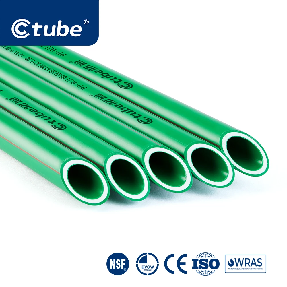
Tubo C es un fabricante líder de soluciones de conductos de PVC de alta calidad, dedicado a ofrecer productos confiables y duraderos para instalaciones eléctricas.
Con sede en China, nos especializamos en la producción de una amplia gama de conductos diseñados para satisfacer las diversas necesidades de varias industrias, al mismo tiempo que garantizamos el cumplimiento de los estándares internacionales.
Nuestro conducto rígido de PVC cumple con rigurosas certificaciones como UL 651, AS/NZS 2053 y CSA, garantizando un rendimiento, durabilidad y seguridad excepcionales en diferentes regiones.
¡Gracias por leer! Esperamos que esta publicación haya sido útil para tu proyecto. Te deseamos mucho éxito en todo tu trabajo. No dudes en contactarnos si tienes alguna necesidad o consulta.
Preguntas frecuentes
1. ¿Cómo se compara el conducto rígido con el conducto flexible?
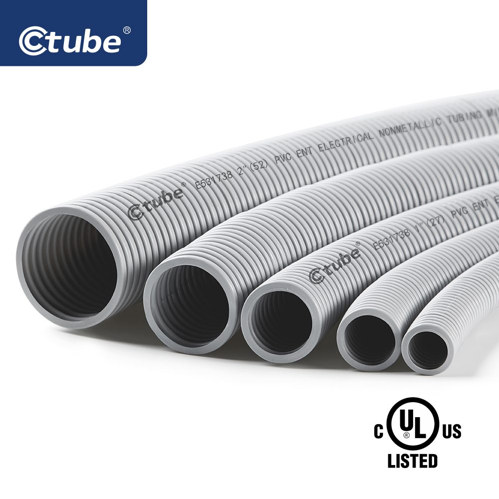
El conducto rígido ofrece mayor protección debido a su estructura sólida, lo que lo hace ideal para entornos con gran estrés mecánico o exposición a humedad y productos químicos.
El conducto flexible es más fácil de instalar y permite el movimiento, lo que lo hace más adecuado para áreas donde se necesita flexibilidad.
2. ¿Cómo se asegura el conducto rígido durante la instalación?
Los conductos rígidos se fijan mediante distintos tipos de fijaciones, como abrazaderas, soportes y correas, según el entorno de instalación (interior, exterior o subterráneo). Estas fijaciones garantizan que el conducto permanezca firmemente en su lugar y protegen el cableado en el interior.
3. ¿Cómo doblar una esquina con conducto eléctrico rígido?
Los accesorios para conductos desempeñan un papel fundamental para garantizar giros suaves en los sistemas de conductos rígidos. Los accesorios más comunes incluyen codos y curvas de barrido, diseñados para crear giros de 90 grados o en ángulo, como ángulos de 45 grados y 22,5 grados. Los conectores en T también se utilizan con frecuencia para permitir que los conductos se ramifiquen en diferentes direcciones.
Entre los conductos rígidos, los EMT (tubos metálicos eléctricos) son los más fáciles de doblar. Las herramientas como un resorte para conductos o una dobladora de conductos son esenciales para realizar curvas precisas, lo que garantiza una alineación e instalación adecuadas.