1. Introduction : comprendre les conduits électriques rigides
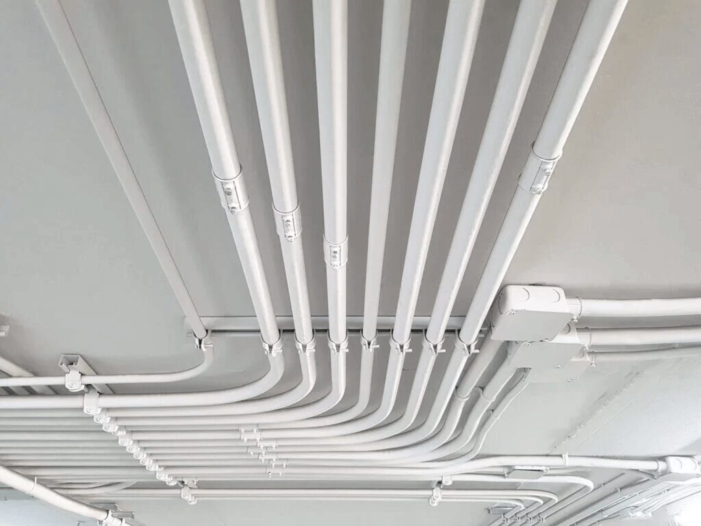
Dans le domaine des systèmes électriques, les conduits jouent un rôle essentiel pour garantir la sécurité, la longévité et la fonctionnalité.
Les conduits électriques servent de canaux de protection pour le passage des câbles électriques, les protégeant ainsi des dommages physiques, de l'humidité, des produits chimiques et autres facteurs environnementaux.
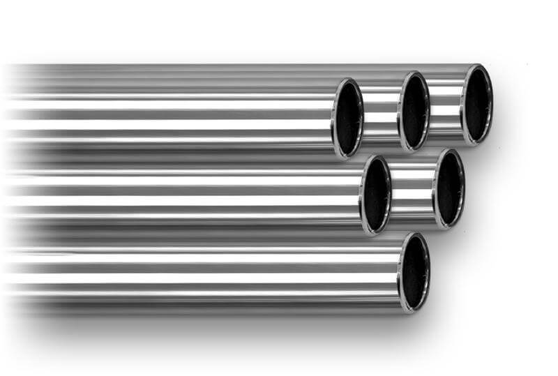
Parmi les différents types de conduits disponibles, le conduit électrique rigide se distingue par sa robustesse et son adéquation aux applications industrielles et résidentielles.
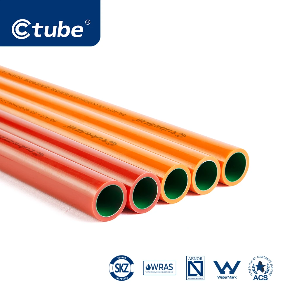
Les conduits électriques rigides se déclinent en de nombreux modèles, chacun conçu pour répondre à des besoins spécifiques en fonction du matériau et de l'application. Parmi les principaux matériaux utilisés, on trouve le PVC (polychlorure de vinyle), l'acier galvanisé, l'aluminium et le RTRC (conduit en résine thermodurcissable renforcée). Chaque matériau présente des avantages uniques, ce qui rend les conduits rigides polyvalents et adaptés à une grande variété d'environnements et d'exigences de projets. À la fin de cet article, vous comprendrez parfaitement ce qu'est un conduit électrique rigide, pourquoi il est un composant essentiel des systèmes électriques modernes et comment l'intégrer à votre prochain projet pour optimiser la sécurité, l'efficacité et la conformité.
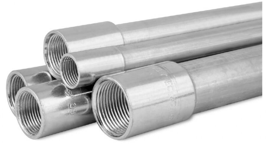
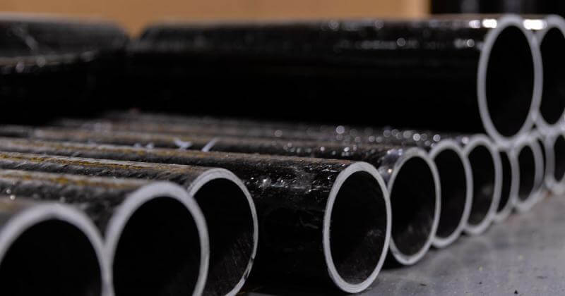
Conduit métallique rigide comprend des types comme les conduits métalliques rigides (RMC), les conduits métalliques intermédiaires (IMC) et les tubes métalliques électriques (EMT), connus pour leur résistance et leur durabilité, ce qui les rend adaptés à une utilisation industrielle et extérieure.Conduit rigide en plastique, tel que le polychlorure de vinyle rigide (PVC), est léger, résistant à la corrosion et couramment utilisé dans des environnements où la protection contre l'humidité est essentielle, comme les installations souterraines.
En plus, conduit RTRC, Fabriqué à partir de fibre de verre, il offre une excellente isolation électrique, une résistance thermique et une protection contre la corrosion, ce qui en fait un choix idéal pour les applications nécessitant des matériaux non conducteurs et à haute résistance.
Dans l’article suivant, nous présenterons les détails des conduits rigides fabriqués à partir de différents matériaux.
2. Types de conduits électriques rigides – Introduction détaillée
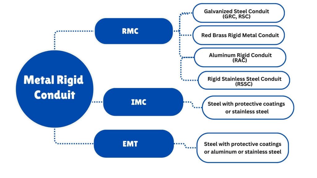
RMC est disponible dans les matériaux suivants :
• Acier avec revêtements protecteurs
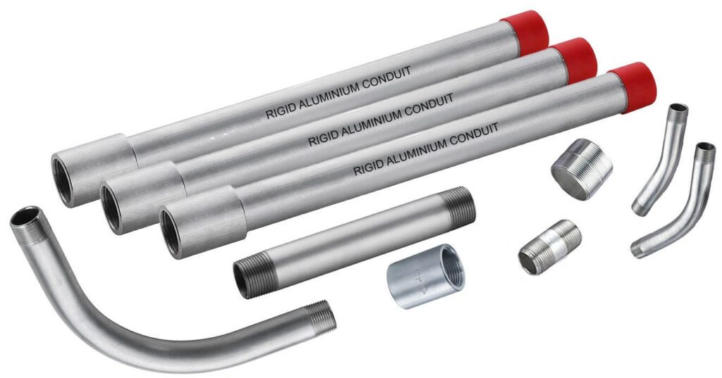
• Aluminium
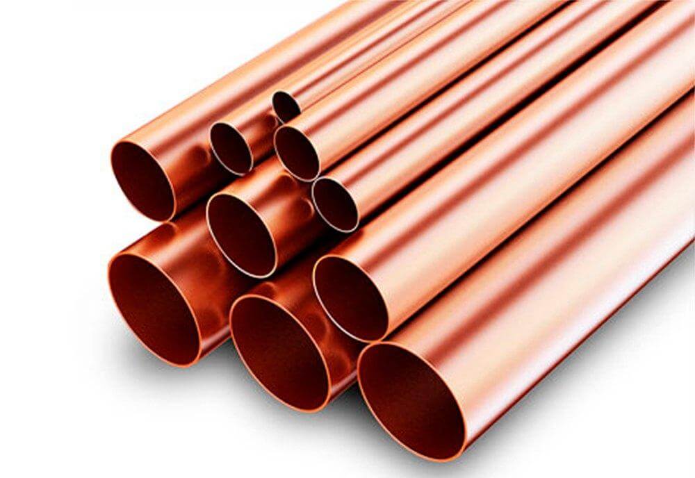
• Laiton rouge
• Acier inoxydable
Matériaux et structure
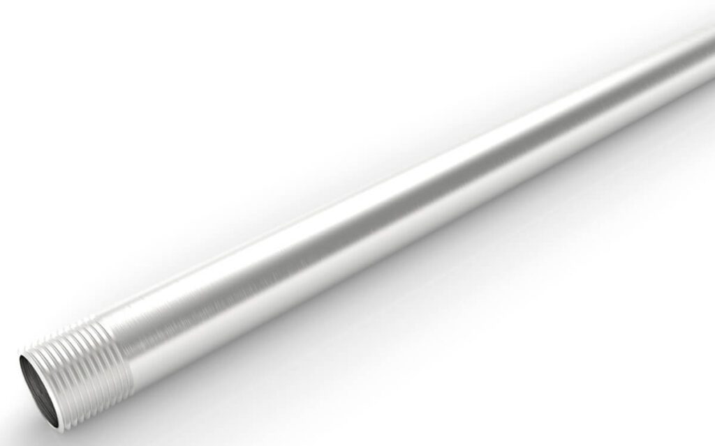
Chaque tube utilisé pour le conduit rigide en acier (RSC) doit être en acier, en veillant à ce qu'il soit droit et qu'il présente une section transversale circulaire.
| Désignateur métrique | Diamètre extérieur (mm) | Taille du commerce | Diamètre extérieur, a (dans) |
|---|---|---|---|
| 12b | 17.15 | 3/8b | 0.675 |
| 16 | 21.34 | 1/2 | 0.840 |
| 21 | 26.67 | 3/4 | 1.050 |
| 27 | 33.40 | 1 | 1.315 |
| 35 | 42.16 | 1-1/4 | 1.660 |
| 41 | 48.26 | 1-1/2 | 1.900 |
| 53 | 60.33 | 2 | 2.375 |
| 63 | 73.03 | 2-1/2 | 2.875 |
| 78 | 88.90 | 3 | 3.500 |
| 91 | 101.60 | 3-1/2 | 4.000 |
| 103 | 114.30 | 4 | 4.500 |
| 129 | 141.30 | 5 | 5.563 |
| 155 | 168.28 | 6 | 6.625 |
a Tolérances : Tailles commerciales 12–41 (3/8–1-1/2) ± 0,38 mm (±0,015 po). Tailles commerciales 53–155 (2–6) ± 1%.
b Aux États-Unis, le calibre 12 (3/8) est autorisé pour des applications spécifiques. Au Canada, le calibre 12 (3/8) n'est pas autorisé selon la partie I du Code canadien de l'électricité.
Coutures soudées
Le procédé de soudage des tubes RMC doit répondre à des critères stricts afin de garantir la sécurité et la fonctionnalité.
Les soudures ne doivent pas comporter de garnitures métalliques, d'arêtes vives ou de saillies susceptibles de gêner le câblage interne ou le processus d'installation.
Un léger bourrelet le long de l'intérieur de la couture est autorisé, à condition qu'il soit lisse et ne dépasse pas 0,38 mm (0,015 po) de hauteur pour les tailles commerciales 12 à 53 (3/8 po à 2 po) ou 0,51 mm (0,020 po) pour les tailles commerciales 63 à 155 (2 ½ po à 6 po).
Exigences standard en matière de longueur et de poids
La longueur standard des conduits droits zingués ou des tubes filetés nus à revêtir d'un matériau alternatif résistant à la corrosion, y compris un raccord, doit respecter les spécifications détaillées dans le tableau ci-après.
Ces tableaux présentent les dimensions et les poids des conduits conformes aux normes indiquées.
| Désignateur métrique | Longueur du conduit droita (mm) |
Poids minimal admissible de 10 longueurs de conduit avec dix raccords, (kg) Conduit fini revêtu de zincb |
Poids minimal admissible de 10 longueurs de conduit avec dix raccords, (kg) Tube fileté nuc |
Taille du commerce | Longueur du conduit droit Pieds et poucesa ±1/4 |
Poids minimal admissible de 10 longueurs de conduit avec dix raccords (lb) Conduit fini revêtu de zincb |
Poids minimal admissible de 10 longueurs de conduit avec dix raccords (lb) Tube fileté nuc |
|---|---|---|---|---|---|---|---|
| 12d | 3035 | 23.4 | 22.6 | 3/8 | 9′–11 1/2″ | 51.5 | 48.6 |
| 16 | 3030 | 35.8 | 34.4 | 1/2 | 9′–11″ | 78.9 | 75.8 |
| 21 | 3030 | 47.6 | 45.5 | 3/4 | 9′–11″ | 104.9 | 100.3 |
| 27 | 3030 | 69.4 | 65.8 | 1 | 9′–11″ | 153.0 | 145.1 |
| 35 | 3025 | 91.2 | 87.8 | 1-1/4 | 9′–11″ | 201.0 | 193.5 |
| 41 | 3025 | 112.9 | 109.4 | 1-1/2 | 9′–11″ | 249.0 | 241.2 |
| 53 | 3035 | 150.4 | 144.3 | 2 | 9′–11 1/2″ | 331.6 | 318.1 |
| 63 | 3010 | 209.6 | 203.4 | 2-1/2 | 9′–10 1/4″ | 462.0 | 448.4 |
| 78 | 3010 | 239.0 | 233.4 | 3 | 9′–10 1/4″ | 527.0 | 514.8 |
| 91 | 3010 | 274.1 | 268.4 | 3-1/2 | 9′–10 1/4″ | 604.4 | 591.5 |
| 103 | 2995 | 312.0 | 305.3 | 4 | 9′–10″ | 687.6 | 672.9 |
| 129 | 2995 | 591.7 | 578.6 | 5 | 9′–10″ | 1304.9 | 1275.6 |
| 155 | 2995 | 797.1 | 781.4 | 6 | 9′–10″ | 1757.0 | 1722.7 |
a Les longueurs indiquées sont conçues pour produire une longueur de conduit de 3,05 m (10 pi) lorsqu'un raccord de conduit à filetage droit est fixé.
b Ce conduit est protégé par un revêtement en zinc ou à base de zinc, composé principalement de zinc.
c Ce conduit est conçu pour être protégé par un revêtement alternatif résistant à la corrosion.
d Aux États-Unis, le calibre 12 (3/8) est autorisé pour des applications spécifiques. Au Canada, le calibre 12 (3/8) n'est pas autorisé selon la partie I du Code canadien de l'électricité.
Exigences de test
Essais de tubes de conduits rigides en acier
Le processus de test des tubes consiste à plier un échantillon de la plus petite taille disponible dans le commerce en un quart de cercle autour d'un mandrin, d'abord à température ambiante, puis après l'avoir conditionné à 0°C (32°F) pendant 60 minutes.
Le tube ne doit présenter aucune fissure ni rupture de soudure. Si le tube possède un revêtement non métallique et est conçu pour des températures inférieures à 0 °C, l'essai est réalisé à cette température inférieure.
| Revêtements | Tests | Article # |
|---|---|---|
| Zinc | Test de flexion Cold Bend Test de revêtement de zinc |
6.2.1.1 6.2.1.3 6.2.2 |
| Résistance alternative à la corrosion | Test de flexion Cold Bend Lumière ultraviolette et eau Brouillard salé CO₂–SO₂–Air humide traction Adhésion Propagation de la flamme |
6.2.1.1 6.2.1.3 6.2.4.3 6.2.4.5 6.2.4.6 6.2.4.8 6.2.4.9 6.2.4.11 |
| Matériau non métallique résistant à la corrosion (en plus de ce qui précède) | Courant d'assemblage, de flexion, de résistance, de traction et de défaut Continuité électrique Identification des composés Impact froid |
5.3.3.2 5.3.5.2 6.2.1.5 6.2.1.0 |
| Organique | Test de flexion Cold Bend Identification des composés Élasticité Test à l'air chaud et humide |
6.2.1.1 6.2.1.3 6.2.1.5 6.2.3.5 6.2.3.2 |
| Revêtements supplémentaires | Effets néfastes sur le revêtement primaire Ajustement des accouplements Continuité électrique Propagation de la flamme |
5.3.5.2 5.3.5.2 5.3.5.2 6.2.4.11 |
| Traitement de surface | Non applicable si l'épaisseur est inférieure à 0,038 mm (0,00015 po). | 5.3.6.1 |
Essais de revêtement des conduits rigides en acier
Le tableau ci-dessous présente différents tests pour divers types de revêtements appliqués aux tubes, notamment le zinc, les revêtements alternatifs résistants à la corrosion, les revêtements non métalliques, organiques et les revêtements supplémentaires.
Ces tests évaluent les performances du revêtement dans différentes conditions telles que la flexion, l'exposition aux rayons UV, les embruns salés, les basses températures et la continuité électrique.
Un chemin de câbles fileté en acier inoxydable de section circulaire, conçu pour la protection physique et l'acheminement des conducteurs de fils et pouvant servir de conducteur de mise à la terre des équipements lorsqu'il est installé à l'aide de raccords appropriés.
Conduit métallique rigide électrique – Laiton rouge (ERMC-RB)
Conduit métallique rigide électrique – Aluminium (ERMC-A)
| Taille du commerce | Diamètre intérieur nominal (po) | Diamètre extérieur (po) | Épaisseur de paroi (po) | Longueur sans accouplement (pi et po) | Poids minimum (10 pièces avec raccords) (lb) |
|---|---|---|---|---|---|
| 1/2 | 0.632 | 0.840 | 0.104 | 9'11-1/4″ | 27.4 |
| 3/4 | 0.836 | 1.050 | 0.107 | 9'11-1/4″ | 36.4 |
| 1 | 1.063 | 1.315 | 0.126 | 9'11’ | 50.7 |
| 1-1/4 | 1.394 | 1.660 | 0.138 | 9'11’ | 66.2 |
| 1-1/2 | 1.624 | 1.900 | 0.138 | 9'11’ | 86.2 |
| 2 | 2.067 | 2.375 | 0.154 | 9'10-1/2″ | 125.0 |
| 2-1/2 | 2.489 | 2.875 | 0.193 | 9'10-1/2″ | 182.5 |
| 3 | 3.068 | 3.500 | 0.225 | 9'10-1/4″ | 236.8 |
| 3-1/2 | 3.570 | 4.000 | 0.245 | 9'10-1/4″ | 358.7 |
| 4 | 4.032 | 4.500 | 0.265 | 9'10’ | 454.9 |
| 5 | 5.073 | 5.563 | 0.245 | 9'10’ | 454.9 |
| 6 | 6.093 | 6.625 | 0.266 | 9'10’ | 604.4 |
| Taille du commerce | Diamètre extérieur (po) Max |
Diamètre extérieur (po) Min |
Épaisseur de paroi (po) Max |
Épaisseur de paroi (po) Min |
Diamètre intérieur nominal (po) | Longueur sans accouplement (pi et po) |
|---|---|---|---|---|---|---|
| 1/2 | 0.820 | 0.810 | 0.085 | 0.070 | 0.659 | 9'11-1/4″ |
| 3/4 | 1.034 | 1.024 | 0.090 | 0.075 | 0.863 | 9'11-1/4″ |
| 1 | 1.295 | 1.285 | 0.100 | 0.085 | 1.063 | 9'11’ |
| 1-1/4 | 1.645 | 1.630 | 0.105 | 0.085 | 1.448 | 9'11’ |
| 1-1/2 | 1.890 | 1.875 | 0.115 | 0.090 | 1.683 | 9'11’ |
| 2 | 2.367 | 2.352 | 0.115 | 0.095 | 2.150 | 9'11’ |
| 2-1/2 | 2.867 | 2.847 | 0.160 | 0.140 | 2.575 | 9'10-1/2″ |
| 3 | 3.486 | 3.466 | 0.160 | 0.140 | 3.176 | 9'10-1/2″ |
| 3-1/2 | 3.981 | 3.961 | 0.160 | 0.140 | 4.161 | 9'10-1/4″ |
| 4 | 4.476 | 4.456 | 0.160 | 0.140 | 4.166 | 9'10-1/4″ |
• Acier avec revêtements protecteurs
• Aluminium
La surface intérieure doit être recouverte de zinc ou d'un revêtement organique. Ce revêtement intérieur doit conserver une surface lisse et continue, les variations mineures dues à un écoulement irrégulier du revêtement étant considérées comme acceptables.
| Taille du commerce | Désignateur métrique | Longueur maximale (pi) | Longueur maximale (m) |
|---|---|---|---|
| 1/2 – 3/4 | 16 – 21 | 10′ 1/4″ | 3.05 |
| 1 – 2 | 27 – 53 | 15′ 1/4″ | 4.58 |
| 2-1/2 – 4 | 63 – 103 | 20′ 1/4″ | 6.10 |
Article 342 Conduit métallique intermédiaire mentionnét IMC est disponible dans les matériaux suivants :
- Acier avec revêtements protecteurs
- Aluminium
| Taille du commerce | Désignateur métrique | Diamètre extérieur (po) | Diamètre intérieur (po) | Épaisseur de paroi (po) | Poids minimal de l'aluminium (lb/pi) | Poids minimal de l'acier inoxydable (lb/pi) |
|---|---|---|---|---|---|---|
| 1/2 | 16 | 0,705 ±0,005 | 0.622 | 0.042 | 0.099 | 0.300 |
| 3/4 | 21 | 0,922 ±0,005 | 0.824 | 0.049 | 0.159 | 0.500 |
| 1 | 27 | 1,163 ±0,005 | 1.049 | 0.057 | 0.221 | 0.700 |
| 1-1/4 | 35 | 1,510 ±0,005 | 1.380 | 0.065 | 0.381 | 1.100 |
| 1-1/2 | 41 | 1,740 ±0,005 | 1.610 | 0.065 | 0.430 | 1.200 |
| 2 | 53 | 2,197 ±0,005 | 2.067 | 0.065 | 0.484 | 1.380 |
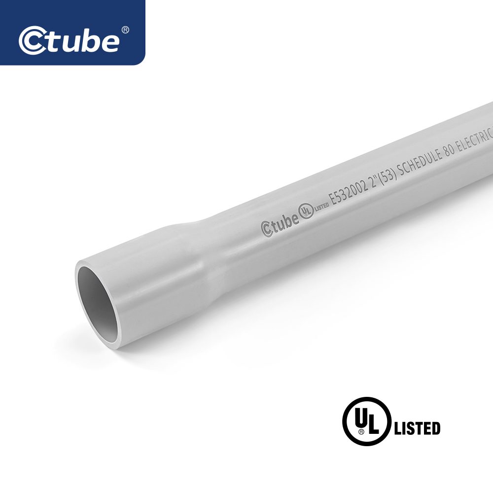
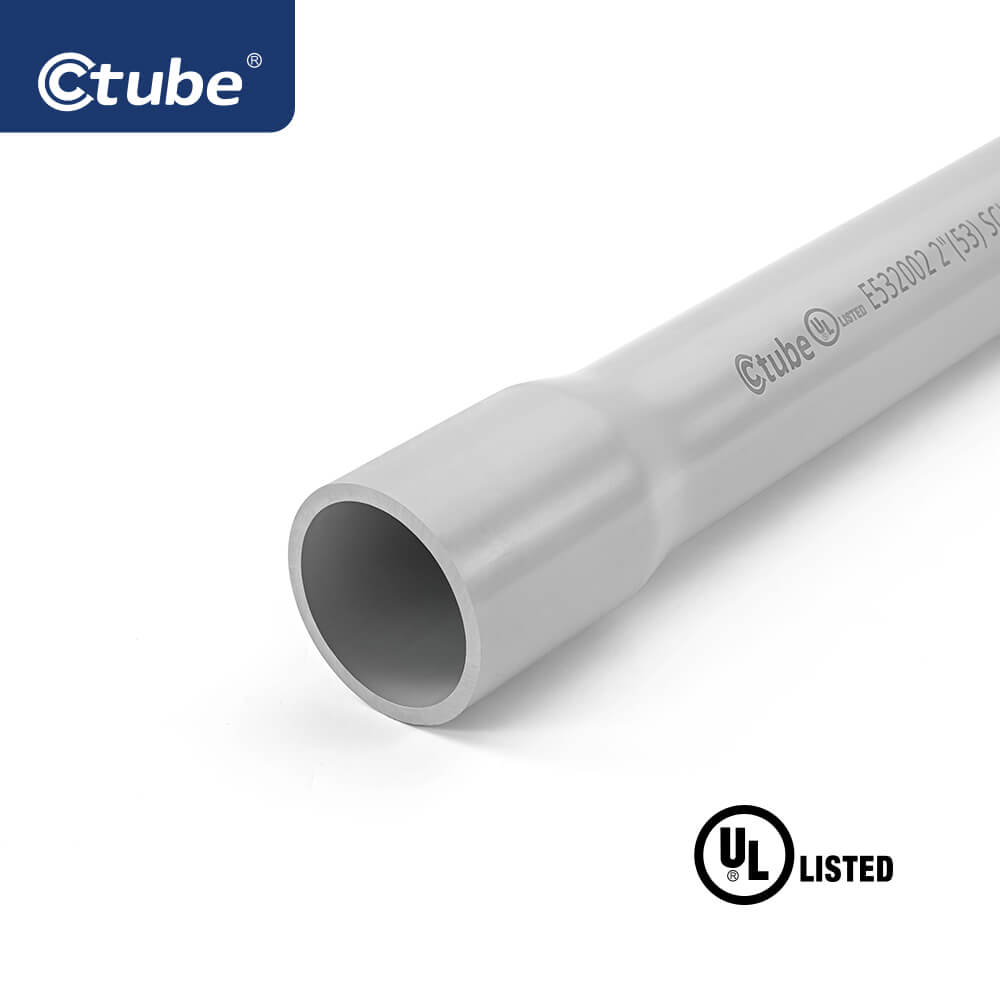
Test pour conduit rigide en PVC
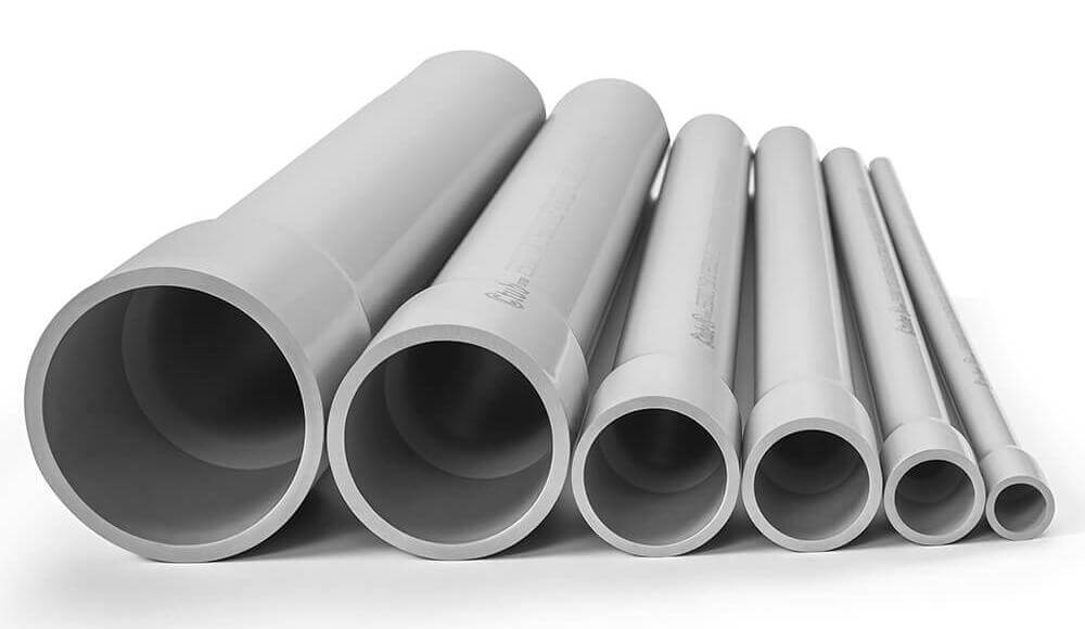
Les conduits de type Schedule 40 et Schedule 80 possèdent des diamètres extérieurs et des épaisseurs de paroi minimales définis pour chaque dimension commerciale. Ces caractéristiques garantissent l'intégrité structurelle pour diverses applications.
Les échantillons de conduits sont testés selon la norme ASTM D 638. Les échantillons vieillis doivent conserver 95 % de la résistance à la traction des échantillons non vieillis. La résistance minimale est de 5 000 psi pour les conduits de type Schedule 40/80 et de 4 000 psi pour les conduits de type A et EB.
Dix échantillons de conduits de 15 cm (6 pouces) sont testés par chute de poids. Trois d'entre eux au maximum peuvent se fissurer ou se déchirer de plus de 0,8 mm (1/32 pouce). Différents poids sont utilisés : 9 kg (20 lb) pour les conduits SCH 40, de type A et EB ; 34 kg (75 lb) pour les conduits SCH 80.
Le conduit doit s'éteindre de lui-même en moins de 5 secondes après exposition à une flamme et ne pas enflammer les matériaux environnants. Ce test est similaire à la norme UL 94 V-0 et exige une résistance élevée au feu et l'absence de gouttes enflammées.
Les conduits ne doivent pas se déformer ni se rompre sous la pression exercée entre les plaques d'acier. Les échantillons aplatis doivent conserver au moins 70% de leur diamètre intérieur initial.
La résistance à l'écrasement mesure la capacité d'un matériau à supporter des forces de compression constantes (par exemple, la pression du sol). La résistance aux chocs mesure sa réaction aux chocs ou aux chutes soudaines. Ces deux propriétés sont essentielles dans différentes conditions d'utilisation.
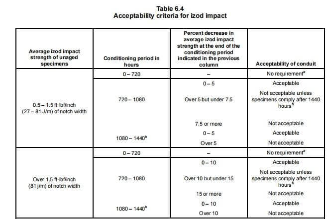
Pour les normes Schedule 40 et 80, les essais d'exposition à la lumière solaire comprennent la mesure de la résistance aux chocs Izod (≥ 0,5 pi-lbf/po). Les échantillons sont testés pendant des périodes de 720 à 1 440 heures selon la méthode ASTM D 256 afin de garantir leur durabilité sous rayonnement UV.
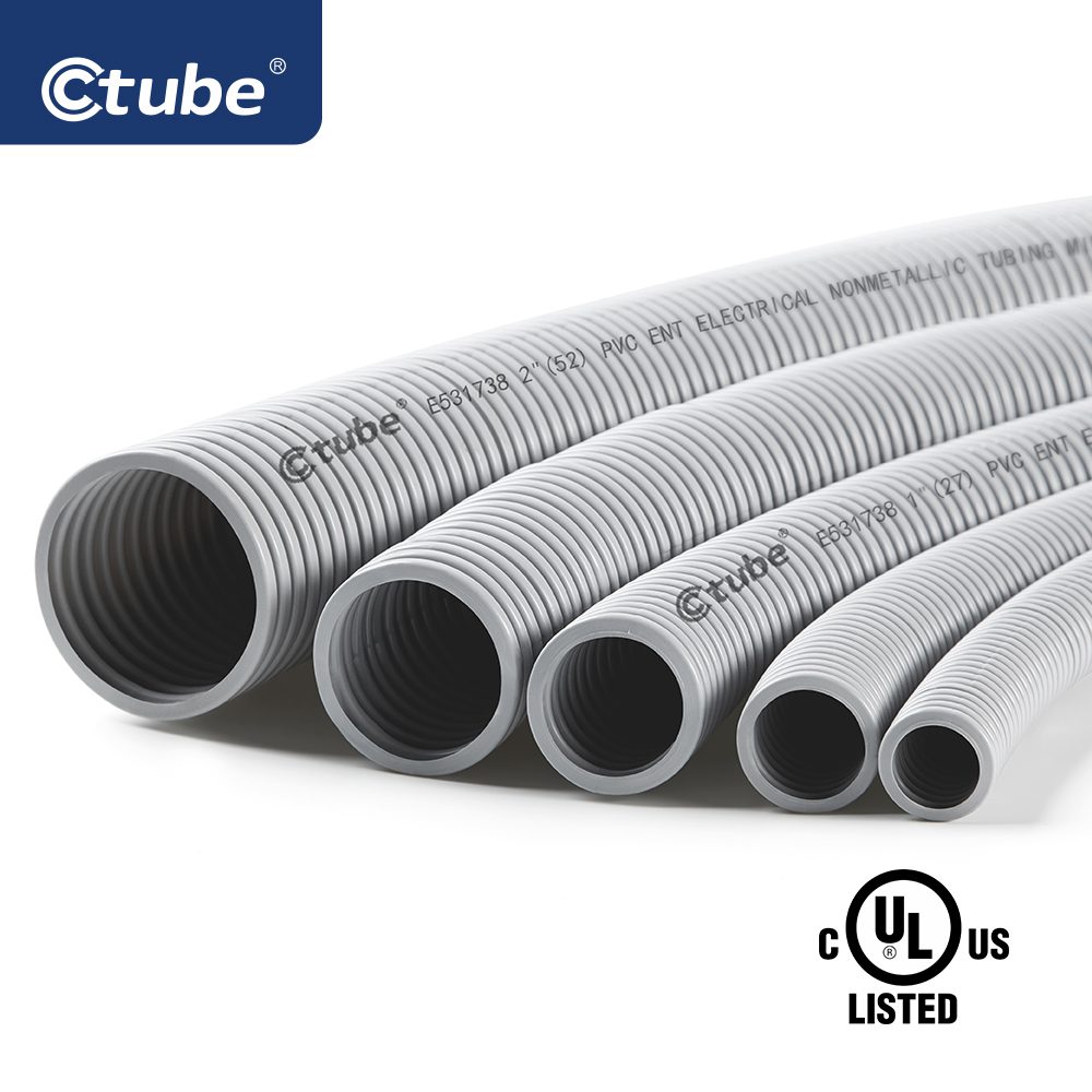
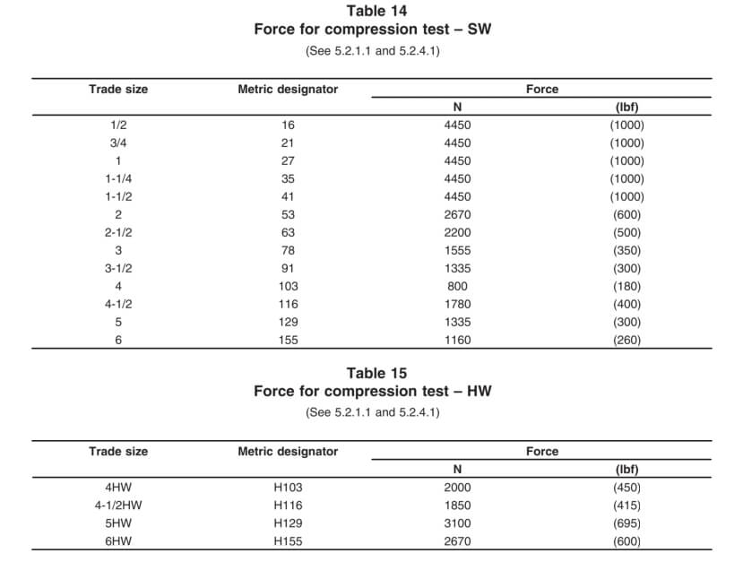
Les types sont définis par le système de diamètre et l'épaisseur de paroi :
- IDENTIFIANT: diamètre intérieur
- IPS : Dimensions des tuyaux en fer (diamètre extérieur)
- Épaisseur de paroi : SW (Standard), MW (Moyen), HW (Lourd), XW (Très Lourd)


Applications :
- En surface : UL 2515
- Souterrain: UL 2420
Chaque échantillon est testé pour la durée de la flamme après application de la flamme : celle-ci ne doit pas dépasser 30 secondes après les quatre premières applications de flamme, ni 60 secondes après la cinquième.
L'optionnel FT4 L'essai à la flamme est l'un des plus rigoureux et est exigé pour certaines constructions incombustibles au Canada. Il consiste à exposer le patient à un 70 000 BTU/heure Flambez pendant 20 minutes.
Critères de réussite : La longueur carbonisée ne doit pas dépasser 1,5 m (5 pi) du bas du brûleur (CSA C22.2 n° 38).
Essais de qualification pour les conduits en résine thermodurcissable renforcée (RTRC)
3. Étude des exigences en matière de profondeur d'enfouissement des conduits électriques rigides

Dans le domaine des installations électriques, la profondeur d'enfouissement appropriée des conduits est primordiale pour garantir la sécurité, la conformité et la durabilité. Les conduits électriques rigides, y compris les conduits métalliques rigides (RMC), les conduits non métalliques comme le PVC et les conduits en fibre de verre, ont des exigences de profondeur d'enfouissement spécifiques dictées à la fois par le National Electrical Code (NEC) et les codes du bâtiment locaux.
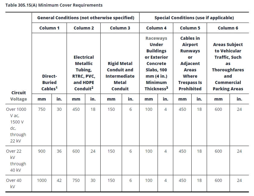
Remarques :
1. Couverture doit être définie comme la distance la plus courte en millimètres (pouces) mesurée entre un point sur la surface supérieure de tout conducteur, câble, conduit ou autre chemin de câbles enterré directement et la surface supérieure du niveau fini, du béton ou d'un revêtement similaire.
2. Des profondeurs moindres seront autorisées lorsque les câbles et les conducteurs remontent pour des terminaisons ou des épissures ou lorsque l'accès est autrement requis.
3. Lorsque la présence de roche solide empêche de respecter les profondeurs d'enfouissement spécifiées dans ce tableau, le câblage doit être installé dans une goulotte métallique ou non métallique autorisée pour l'enfouissement direct. Les goulottes doivent être recouvertes d'une couche de béton d'au moins 50 mm (2 po) jusqu'à la roche.
4. Dans les établissements industriels, où les conditions d'entretien et de surveillance garantissent que des personnes qualifiées entretiendront l'installation, les exigences minimales de couverture pour les conduits autres que les conduits métalliques rigides et les conduits métalliques intermédiaires peuvent être réduites de 150 mm (6 po) pour chaque 50 mm (2 po) de béton ou équivalent placé entièrement dans la tranchée au-dessus de l'installation souterraine.
5. Câbles enterrés directement : Les câbles souterrains enterrés directement qui ne sont pas enrobés ou protégés par du béton et qui sont enterrés à 750 mm (30 po) ou plus sous le niveau du sol doivent avoir leur emplacement identifié par un ruban d'avertissement placé dans la tranchée au moins 300 mm (12 po) au-dessus des câbles.
6. Tubes métalliques électriques, conduits RTRC, PVC et PEHD : Ces conduites peuvent être homologuées par un organisme de certification agréé comme étant adaptées à l'enfouissement direct sans enrobage. Tous les autres systèmes non métalliques nécessitent une couche de béton de 50 mm (2 po) ou équivalent au-dessus de la conduite, en plus de la profondeur de la table.
7. Canalisations sous les bâtiments ou les dalles de béton extérieures (épaisseur minimale de 100 mm / 4 po) : La dalle doit s'étendre d'au moins 150 mm (6 po) au-delà de l'installation souterraine, et un ruban d'avertissement ou tout autre moyen efficace adapté aux conditions doit être placé au-dessus de l'installation souterraine.
8. Les autres câbles non blindés non couverts par les paragraphes 305.15(A)(1) ou (A)(2) doivent être installés dans un conduit métallique rigide, un conduit métallique intermédiaire ou un conduit non métallique rigide enrobé d'au moins 75 mm (3 po) de béton.
9. Conducteurs émergeant du sol : Ces câbles doivent être installés dans des conduits homologués. Les conduits installés sur les poteaux doivent être en conduit métallique rigide, en conduit métallique intermédiaire, en RTRC-XW, en conduit PVC Schedule 80 ou équivalent, s'étendant de la profondeur de couverture minimale spécifiée dans le tableau 305.15(A) jusqu'à un point situé à 2,5 m (8 pi) au-dessus du niveau fini du sol.
Les facteurs environnementaux influencent considérablement la profondeur d'enfouissement des conduits. Les conditions du sol, telles que la stabilité et la teneur en humidité, peuvent déterminer la profondeur à laquelle un conduit doit être installé pour garantir sa sécurité au fil du temps. Par exemple, dans les sols rocheux ou instables, un enfouissement plus profond peut être nécessaire pour éviter les dommages causés par les mouvements du sol.
Les charges de trafic jouent également un rôle essentiel, notamment dans les zones où les conduits sont installés sous les routes ou les parkings. Dans ce cas, un enfouissement plus profond est souvent nécessaire pour protéger les conduits du poids et des vibrations des véhicules et des équipements lourds.
4. Directives d'installation pour différents types de conduits rigides
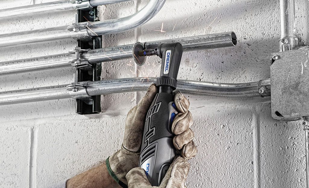
Avant de commencer, rassemblez les outils et matériaux suivants :
• Outils de coupe : Scie à métaux ou cutter à rouleau (si une découpe est nécessaire).
• Fraise: Pour enlever les bavures à l'intérieur du conduit après la coupe.
• Cintreuse de conduits : Pour réaliser des pliages précis.
• Clés à molette : De taille appropriée.
• Composé d'étanchéité pour filetage ou peinture anticorrosion : Pour protéger les fils si nécessaire.
Vérifiez également que vous disposez de tous les raccords, coupleurs et connecteurs nécessaires pour assurer une mise à la terre correcte.
• Mesurer et couper : Mesurez la longueur requise et coupez proprement à la scie.
• Rame: Éliminez les bavures à l'intérieur du conduit pour éviter d'endommager les fils.
• Enfilage : Utilisez une filière standard de ¾ pouce par pied (NPT) pour le filetage si nécessaire. Le filetage doit être lisse et propre.
Pour les conduits pré-filetés, ne pas fileter, mais protéger les filets exposés ou endommagés.
• Serrage manuel et finition à la clé : Commencez par serrer à la main, puis serrez à la clé d'un tour complet au-delà du serrage manuel.
• Évitez de trop serrer : Une force excessive peut endommager le filetage et le revêtement. N'utilisez pas de rallonges de clé.
• Pour les raccords sans filetage, enfoncez complètement le conduit dans le raccord et serrez-le avec le couple approprié.
• Plier à la main : Les petites tailles (½ à 1 pouce) peuvent être pliées avec une cintreuse manuelle ; les tailles plus grandes nécessitent des cintreuses mécaniques ou électriques.
• Précision: Marquez les coudes ; évitez de dépasser 90° entre les points de traction.
• Évitez les nœuds : Évitez d'aplatir ou de plier le câble, car cela réduit l'espace et complique le tirage des fils.
• Pour les conduits pré-filetés, évitez d'endommager le filetage lors du cintrage.
• Utilisez des sangles, des supports ou des pinces pour fixer les conduits aux murs, aux plafonds ou aux éléments de structure.
• Pour les installations verticales, fixez le conduit à son extrémité supérieure pour éviter qu'il ne s'affaisse.
• Pour les conduits passant du béton au sol ou souterrains, appliquez des revêtements, des gaines ou des conduits revêtus de PVC approuvés pour une protection supplémentaire.
• Lors de l'installation, inspecter les revêtements appliqués en usine afin de détecter tout dommage.
• Appliquer, au besoin, des composés anticorrosion, de la peinture riche en zinc ou du ruban adhésif anticorrosion.
• Protéger les filetages réalisés sur le terrain avec des revêtements résistants à la corrosion et électriquement conducteurs.
• Effectuer des tests de continuité pour confirmer la continuité électrique et la mise à la terre.
• Vérifiez l’étanchéité de tous les raccords de conduits et assurez-vous de la solidité des supports.
• Vérifier que les revêtements protecteurs restent intacts et que des protections supplémentaires sont appliquées au besoin.
Avant de commencer, rassemblez les outils et matériaux nécessaires pour une installation réussie de conduits en PVC :
Conduit en PVC : le diamètre et la longueur appropriés pour votre projet.
Raccords en PVC : raccords, coudes, boîtes de jonction et autres composants.
Ciment et apprêt PVC : Pour fixer les joints et les raccords.
Coupe-conduit ou scie à métaux : pour couper le conduit à la longueur requise.
Outil d'ébavurage : pour lisser les bords coupés du conduit.
Ruban à mesurer : pour des mesures précises.
Niveau : Pour assurer un alignement correct.
Tire-fil ou ruban de tirage : pour tirer les fils à travers le conduit après l'installation.
Avant de commencer l'installation, planifiez soigneusement le parcours de votre conduit en PVC. Cela comprend la mesure de la distance entre les points où le conduit passera et le repérage des endroits où les coudes, les raccords et les jonctions seront nécessaires.
Mesurer et marquer : utilisez un ruban à mesurer pour déterminer la longueur du conduit en PVC requise pour chaque section et marquez les endroits où les coupes seront effectuées.
Tenez compte de la dilatation et de la contraction : les conduits en PVC se dilatent et se contractent en fonction des changements de température. Vous devrez donc laisser un peu de place pour le mouvement ou installer des raccords de dilatation sur les longues distances.
Couper des conduits en PVC est beaucoup plus facile que couper des conduits métalliques, mais il est toujours important de faire des coupes nettes et précises pour assurer une installation en douceur.
Couper le conduit : Utilisez un coupe-conduit en PVC ou une scie à métaux à dents fines pour couper le conduit aux longueurs mesurées. Assurez-vous que les coupes sont droites et nettes.
Ébavurage des bords : après la coupe, utilisez un outil d'ébavurage ou un couteau utilitaire pour éliminer les bords rugueux ou les bavures à l'intérieur et à l'extérieur du conduit. Cette étape est essentielle pour éviter d'endommager les fils lorsqu'ils sont tirés à travers le conduit.
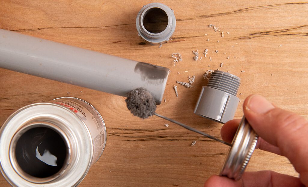
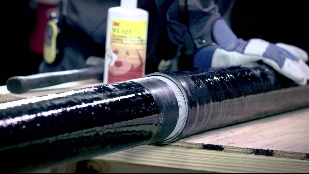
Contrairement aux conduits métalliques, pour lesquels des filetages ou des raccords à vis sont utilisés, les sections de conduits en PVC sont assemblées par un procédé appelé soudage par solvant. Cela implique l'utilisation d'un apprêt et d'un ciment PVC pour coller le conduit et les raccords ensemble.
Appliquer l'apprêt : Tout d'abord, nettoyez les extrémités du conduit et l'intérieur des raccords à l'aide d'un apprêt PVC. L'apprêt ramollit le matériau et le prépare au processus de collage.
Appliquer le ciment PVC : Immédiatement après avoir appliqué l'apprêt, recouvrir les mêmes zones avec du ciment PVC. Veillez à travailler rapidement, car le ciment sèche rapidement.
Assemblez le conduit et les raccords : poussez le conduit dans le raccord, en le tournant légèrement pour assurer une répartition uniforme du ciment. Maintenez les pièces ensemble pendant quelques secondes pour assurer une liaison solide.
Essuyez l'excès de ciment : retirez tout excès de ciment qui s'échappe pendant le processus de connexion. Laissez le joint durcir conformément aux instructions du fabricant avant de le manipuler davantage.
Ce procédé de soudage par solvant crée un joint étanche, ce qui rend le PVC idéal pour les installations extérieures et souterraines où la résistance à l'humidité est essentielle.
Le cintrage des conduits en PVC est différent du cintrage des conduits métalliques. Le PVC peut être plié à chaud pour créer des courbes lisses et personnalisées sans avoir recours à des coudes préfabriqués dans certaines situations.
Chauffer le conduit en PVC : utilisez un pistolet thermique ou un appareil de cintrage en PVC pour chauffer la section du conduit où le cintrage est nécessaire. Veillez à appliquer la chaleur uniformément pour éviter de déformer le conduit.
Faire le coude : Une fois le conduit flexible, pliez-le lentement jusqu'à l'angle souhaité. Maintenez-le en place jusqu'à ce que le conduit refroidisse et conserve sa forme.
Utilisez des coudes préfabriqués : pour la plupart des installations, il est plus facile d'utiliser des coudes en PVC à 90 ou 45 degrés fabriqués en usine, qui sont collés en place à l'aide du même processus de soudage par solvant.
Étant donné que le PVC est plus flexible et léger que les conduits métalliques, il nécessite un support approprié pour éviter tout affaissement ou mouvement au fil du temps.
Installer des colliers ou des pinces pour conduits : soutenez le conduit en PVC à intervalles réguliers en le fixant avec des colliers ou des pinces pour conduits. Suivez les directives du NEC, qui recommandent de soutenir le PVC tous les 3 à 6 pieds, selon le diamètre du conduit.
Permettre la dilatation : les conduits en PVC se dilatent et se contractent en fonction des variations de température. Sur les longueurs plus longues, installez des raccords de dilatation pour permettre le mouvement sans solliciter les joints. Les raccords de dilatation sont essentiels pour les installations extérieures ou exposées au soleil où les fluctuations de température sont importantes.
Une fois le conduit installé et les joints de ciment durcis, vous pouvez tirer les fils à travers le conduit.
Utilisez un ruban de tirage ou une ficelle de tirage : faites passer le ruban de tirage ou la ficelle de tirage dans le conduit, puis fixez solidement les fils au ruban.
Tirez les fils : tirez lentement les fils à travers le conduit, en vous assurant qu'ils ne s'accrochent pas ou ne sont pas endommagés sur les bords rugueux.
Lubrifier si nécessaire : si le conduit est long ou comporte plusieurs coudes, utilisez un lubrifiant de tirage de fil pour réduire la friction et faciliter le processus de tirage de fil.
Une fois les fils tirés et le système installé, effectuez une inspection finale pour vous assurer que tout est installé correctement et en toute sécurité.
Vérifiez les connexions : assurez-vous que tous les joints soudés au solvant sont solides et qu'aucun raccord n'est desserré.
Vérifier les supports : Confirmez que toutes les sangles et pinces de conduit sont correctement espacées et fixées.
Pour une installation réussie des conduits RTRC, rassemblez les outils et matériaux suivants :
- Conduit RTRC : Diamètre et longueur appropriés des conduits.
- Raccords RTRC : Raccords, coudes et autres composants nécessaires.
- Époxy ou adhésif bi-composant : Pour coller les sections de conduit et les raccords.
- Scie à métaux ou scie à denture fine : Pour couper le conduit à la bonne dimension.
- Outil d'ébavurage ou papier de verre : Pour lisser les bords coupés.
- Ruban à mesurer et niveau : Pour des mesures et un alignement précis.
- Tirer sur une ficelle ou un aiguille de tirage : Pour faire passer les câbles dans la gaine après l'installation.
- Pistolet thermique : Pour les composants thermorétractables, si nécessaire.
Comme pour tout système de conduits, commencez par planifier l'itinéraire et la disposition de l'installation du RTRC. Identifiez les points où les conduits changeront de direction, où les raccords seront nécessaires et où les points d'accès ou les boîtes de jonction doivent être placés.
Mesurer et marquer : Utilisez un mètre ruban pour déterminer avec précision les longueurs de conduit nécessaires et marquez les endroits où des coupes devront être effectuées.
La coupe du conduit RTRC est similaire à la coupe du PVC, mais la composition du matériau nécessite une manipulation soigneuse pour éviter d'endommager les fibres.
Coupez le conduit : Utilisez une scie à métaux, une scie sauteuse ou toute autre scie à denture fine pour couper le conduit à la longueur souhaitée. Veillez à ce que la coupe soit droite pour permettre un assemblage correct.
Ébavurer les bords : Après la coupe, lissez les bords intérieurs et extérieurs à l'aide d'un outil d'ébavurage ou de papier de verre. Cela évite d'endommager l'isolation des fils.
Contrôle de la poussière : Lors de la découpe de RTRC, utilisez des EPI tels que des gants, une protection oculaire et un masque anti-poussière ou un respirateur pour gérer la poussière de fibre de verre.
Les conduits RTRC sont assemblés à l'aide d'adhésifs ou d'un époxy bi-composant conçu pour les systèmes de conduits en fibre de verre.
Préparer les surfaces : Nettoyez les extrémités des conduits et l'intérieur des raccords pour enlever la poussière, la saleté et l'huile.
Appliquer l'adhésif : Utilisez l'époxy recommandé. Appliquez-le généreusement sur les deux surfaces à assembler.
Rejoignez et définissez : Insérez le conduit dans le raccord en le vissant. Maintenez la position brièvement jusqu'au début de la prise.
Temps de séchage : Laisser durcir complètement conformément aux instructions du fabricant avant d'appliquer une charge ou une contrainte.
Le conduit RTRC nécessite un support adéquat, notamment dans les applications horizontales :
- Utilisez des sangles, des supports ou des pinces homologués tous les 1,8 à 3 mètres conformément aux exigences du NEC.
- Joints de dilatation : Prévoir des raccords de dilatation sur les longues distances ou dans les zones sujettes à des variations de température.
Le cintrage des conduits RTRC n'est généralement pas effectué sur site :
- Utilisez des coudes et des courbes préfabriqués (par exemple, 90°, 45°), assemblés avec de l'adhésif.
- Pas de cintrage à chaud : La chaleur endommage l'intégrité structurelle du RTRC.
Une fois l'adhésif durci, procédez à l'installation des câbles :
- Utilisez un tire-fil ou une ficelle pour guider les câbles dans la gaine.
- Appliquez du lubrifiant sur les tronçons longs ou complexes pour faciliter la traction.
- Assurez-vous que la mise à la terre et la liaison soient conformes aux normes NEC, car le RTRC n'est pas conducteur.
Avant la mise sous tension du système :
- Inspectez tous les joints adhésifs pour confirmer la bonne adhérence.
- Vérifiez que tous les supports sont en place et aux intervalles corrects.
5. Conclusion
| Caractéristiques | RMC | CMI | EMT | PVC | RTRC |
|---|---|---|---|---|---|
| Coût | Coût initial le plus élevé | Coût modéré | Inférieur à RMC et IMC | Coût initial le plus bas | Coût modéré à élevé |
| Durabilité | Très durable, très résistant | Durable, mais plus léger que le RMC | Moins durable que le RMC et l'IMC | Durable, mais pas aussi solide que le métal | Très durable, résistant aux chocs |
| Résistance à la corrosion | Bon avec les revêtements | Mieux avec des revêtements | Sujet à la corrosion à moins d'être revêtu | Excellent, naturellement résistant | Excellent, très résistant |
| Facilité d'installation | Lourd, nécessite plus de travail | Modéré, plus léger que le RMC | Le plus simple à installer | Facile, léger et flexible | Facile à installer, léger |
Importance du choix du conduit adapté aux différents environnements
Pour les applications hors sol, privilégiez les options résistantes aux UV pour résister aux rayons du soleil, tandis que pour les installations souterraines, concentrez-vous sur la résistance à l'humidité et à la corrosion pour vous protéger contre les facteurs environnementaux.
Zones sujettes à l'humidité
Dans les environnements où l'humidité est fréquente, comme les sous-sols, les salles de bains ou les installations extérieures, il est essentiel de choisir des conduits résistants à l'eau.
Des solutions comme les conduits en PVC ou les conduits spécialisés résistants à l'humidité contribuent à prévenir la corrosion, qui peut entraîner des pannes électriques et des risques pour la sécurité.
De plus, les conduits résistants à l'humidité répondent souvent à des codes spécifiques pour les emplacements humides, garantissant ainsi la conformité aux normes électriques.
Risques de corrosion
Dans les environnements industriels ou commerciaux, les conduits peuvent être exposés à divers produits chimiques, notamment des solvants, des acides ou des produits caustiques.
L'utilisation de conduits fabriqués à partir de matériaux résistants à la dégradation chimique, tels que certains types de conduits en PVC ou en métal, contribue à préserver l'intégrité du câblage.
Ce choix permet non seulement d'éviter d'endommager le conduit lui-même, mais aussi de protéger l'environnement et le personnel contre toute exposition dangereuse.
Dans les zones côtières ou les endroits à forte humidité, il est essentiel de choisir des conduits résistants à la corrosion.
Des solutions comme les conduits en fibre de verre ou en acier inoxydable peuvent résister à des conditions environnementales difficiles, empêchant ainsi une détérioration prématurée et garantissant une fiabilité à long terme.
Ce choix est particulièrement important pour les installations souterraines ou immergées, où l'exposition à l'humidité et aux sels est inévitable.
Températures extrêmes
Les régions qui connaissent des températures extrêmes, qu'elles soient chaudes ou froides, nécessitent des conduits conçus pour résister à de telles conditions.
Par exemple, les conduits conçus pour résister à des températures élevées ou au gel garantissent que le câblage reste fonctionnel sans compromettre la sécurité.
Par grand froid, des conduits flexibles peuvent être nécessaires pour éviter les fissures, tandis que par forte chaleur, des matériaux résistants aux UV peuvent protéger contre l'exposition au soleil.
En examinant attentivement ces facteurs, vous pouvez faire un choix éclairé qui répond à la fois aux besoins de performance et aux normes réglementaires, contribuant ainsi au succès de votre projet.
Ctube est un fabricant de premier plan de solutions de conduits en PVC de haute qualité, dédié à la fourniture de produits fiables et durables pour les installations électriques.
Basés en Chine, nous sommes spécialisés dans la production d'une large gamme de conduits conçus pour répondre aux divers besoins de différentes industries, tout en garantissant la conformité aux normes internationales.
Nos conduits rigides en PVC sont conformes à des certifications rigoureuses telles que UL 651, AS/NZS 2053 et CSA, garantissant des performances, une durabilité et une sécurité exceptionnelles dans différentes régions.
Merci de votre lecture ! Nous espérons que cet article vous a été utile. Nous vous souhaitons beaucoup de succès dans vos projets et restons à votre disposition pour toute question ou besoin concernant vos projets.
FAQ
Comment un conduit rigide se compare-t-il à un conduit flexible ?
Le conduit rigide offre une meilleure protection grâce à sa structure solide, ce qui le rend idéal pour les environnements soumis à de fortes contraintes mécaniques ou à une exposition à l'humidité et aux produits chimiques.
Le conduit flexible est plus facile à installer et permet le mouvement, ce qui le rend plus adapté aux zones où la flexibilité est nécessaire.
Comment les conduits rigides sont-ils fixés lors de l'installation ?
Les conduits rigides sont fixés à l'aide de différents types de fixations, telles que des colliers, des supports et des sangles, en fonction de l'environnement d'installation (intérieur, extérieur ou souterrain). Ces fixations garantissent que le conduit reste fermement en place et protègent le câblage à l'intérieur.
Comment réaliser un virage avec un conduit électrique rigide ?
Les raccords de conduits jouent un rôle crucial pour assurer des virages en douceur pour les systèmes de conduits rigides. Les raccords courants comprennent les coudes et les coudes à balayage, conçus pour créer des virages à 90 degrés ou en angle tels que des angles de 45 degrés et de 22,5 degrés. Les connecteurs en T sont également fréquemment utilisés pour permettre aux conduits de se ramifier dans différentes directions.
Parmi les conduits rigides, les tubes métalliques électriques (EMT) sont les plus faciles à cintrer. Des outils comme un ressort ou une cintreuse de conduits sont essentiels pour réaliser des coudes précis, garantissant un alignement et une installation corrects.