
1. Introduction
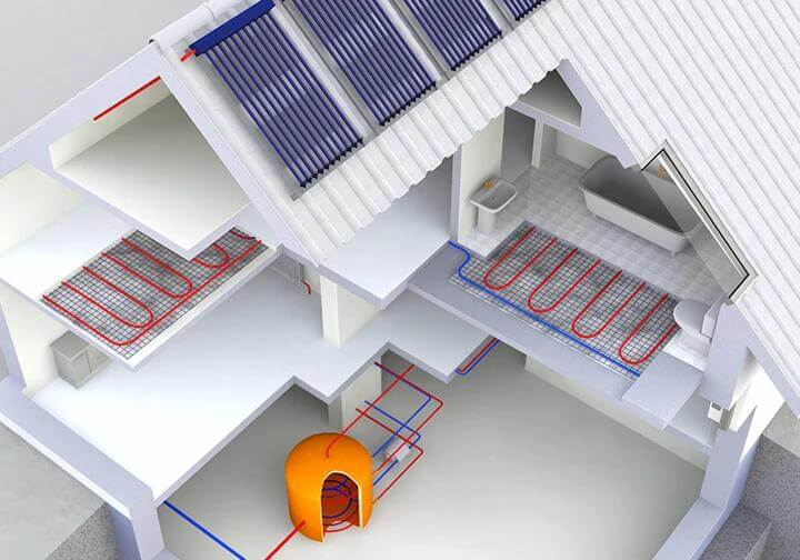
Designing a commercial or residential PE-RT pipe radiant floor heating system isn’t just about laying tubes in concrete. A single miscalculation in loop length, heat loss, or manifold zoning can result in cold spots, burnt-out circulator pumps, or thousands of dollars in concrete tear-outs.
For MEP engineers and HVAC contractors, precision is everything. This guide dives deep into the core engineering principles of PE-RT underfloor heating—from calculating BTU heat loss and flow rates to selecting the right loop layout patterns to avoid costly callbacks.
1.1 Key Takeaways:
- Heat Loss Benchmark: Typical commercial spaces require 25–35 BTU/sq.ft, dictating pipe spacing and flow rates.
- Maximum Loop Lengths: Never exceed 300 ft (90m) for 1/2″ PE-RT pipe to prevent critical pressure drops (Head Loss).
- Flow Rate Precision: Understand how to calculate GPM (Gallons Per Minute) or L/s based on the Delta T (ΔT) of your specific system.
- Material Integrity: Why oxygen barrier (EVOH) PE-RT pipes strictly complying with ISO 22391 and DIN 4726 are mandatory to prevent boiler corrosion.
2. Basic Principles of Radiant Floor Heating Layout
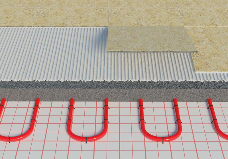
Designing an effective radiant floor heating system begins with understanding how heat is generated, transferred, and distributed within a space. Unlike forced-air systems, radiant heating relies on the principle of heat radiation and conduction, where warm water circulating through embedded pipes transfers heat upward through the floor surface and into the room. This fundamental mechanism makes layout design a critical factor in achieving consistent thermal comfort.
2.1 Heat Loss Calculation: The Foundation of Radiant Design
Before laying a single inch of PE-RT pipe, contractors must determine the heat loss of the space.
- Well-insulated modern buildings: 15–25 BTU/sq.ft (45–80 W/m²)
- Average building consumption: 25–35 BTU/sq.ft (80–110 W/m²)
- High-load areas (large windows/exterior walls): 35+ BTU/sq.ft (110+ W/m²)
The Universal Heat Loss Formula:
Metric: Heat Loss (W) = Area (m²) × U-value (W/m²K) × Temperature Difference (ΔT in °C)
Imperial: Heat Loss (BTU/h) = Area (ft²) × U-value (BTU/h⋅ft²⋅°F) × Temperature Difference (ΔT in °F)
Example: A 500 ft² room with a U-value of 0.15 and a temperature difference of 40°F requires a heating output of: 500 × 0.15 × 40 = 3,000 BTU/h.
2.2 System Flow Rate & Delta T (ΔT)
The flow rate dictates the capacity of the manifold and the sizing of the circulator pump.
- UK/European Systems: Commonly designed with a ΔT of 5-10°C.
- US/North American Systems: Often designed with a ΔT of 10-20°F.
Flow Rate Formulas:
Metric: Flow Rate (L/s) = Heat Output (kW) / (ΔT × 4.18)
Imperial: Flow Rate (GPM) = Heat Output (BTU/h) / (ΔT × 500)
- Procurement & Sizing Example (Imperial): If a room requires 3,000 BTU/h of heat (calculated from section 2.1) and your system operates at a 20°F ΔT, the calculation is:
3,000 / (20 × 500) = 0.3 GPM. Takeaway for Buyers: Knowing this allows procurement managers to verify if the specified PE-RT pipe diameter and manifold flow meters can support 0.3 Gallons Per Minute for that specific loop without excessive pump strain.
2.3 Calculating Required PE-RT Coil Length
Always add an extra 10% for manifold transit (supply/return runs) and cutting waste to prevent mid-loop splicing.
Metric: Pipe Length (m) = [(Total Area (m²) / Pipe Spacing (m)) + Transit Pipe Length (m)] × 1.1
Imperial: Pipe Length (ft) = [(Total Area (ft²) / Pipe Spacing (ft)) + Transit Pipe Length (ft)] × 1.1
- Procurement & Sizing Example (Imperial): Imagine a 500 ft² commercial space. The engineer specifies an 8-inch (0.67 ft) pipe spacing to meet the BTU load, and the manifold is 20 ft away (meaning 40 ft total for supply + return).
- Calculation:
[(500 / 0.67) + 40] × 1.1 - Result:
(746 + 40) × 1.1 = 864.6 feet.Takeaway for Buyers: Instead of ordering standard 300 ft rolls and dealing with dangerous underground splices, a procurement manager will know to order a 1,000 ft continuous PE-RT coil for this specific zone, ensuring zero underground connection risks.
- Calculation:
PE-RT Pipe Length Calculator (Imperial)
PE-RT Pipe Length Calculator (Imperial)
3. Common PE-RT Pipe Layout Patterns
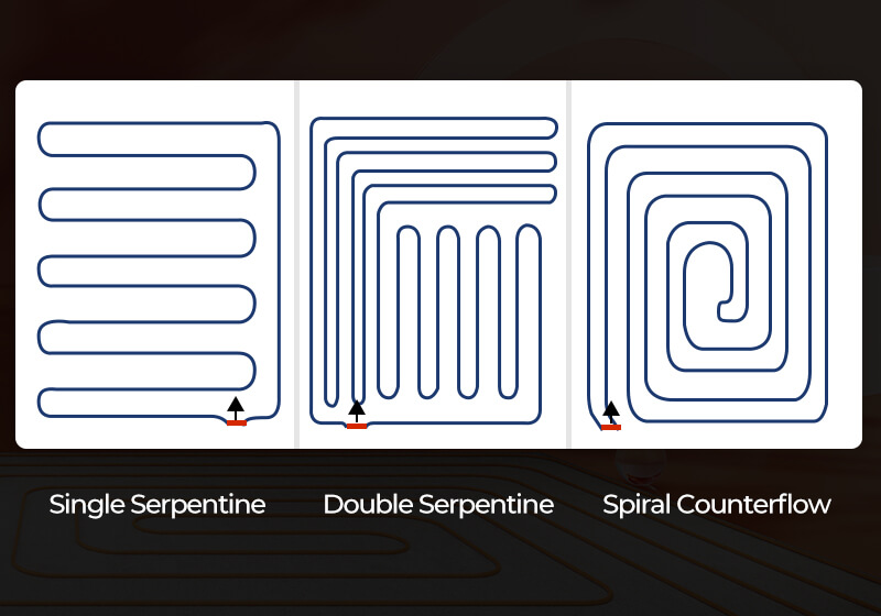
The layout pattern of heating pipes plays a critical role in determining how heat is distributed across the floor surface. Different layout methods can significantly influence temperature uniformity, system efficiency, and installation complexity. In radiant floor heating systems using PE-RT pipes, selecting an appropriate layout pattern is essential for achieving balanced heat output and reliable long-term performance.
Choosing the right pipe layout pattern is not about installer preference or aesthetics—it is a critical engineering decision that dictates hydraulic balancing, floor temperature uniformity, and circulator pump energy consumption.
Using the wrong pattern in a high-heat-loss area (like near massive glass facades) will result in freezing perimeters and overheated center floors. To help contractors and MEP engineers visualize the optimal application, use the reference matrix below:
| Feature / Metric | Serpentine (Snake / Meander Pattern) | Counter-Flow (Snail / Spiral Pattern) |
|---|---|---|
| Heat Distribution | Uneven: The floor is hottest near the manifold and progressively cooler at the end of the loop. | Highly Uniform: Supply (hot) and return (cooler) lines alternate side-by-side, balancing the floor temp. |
| Bending Stress | High: Requires tight 180° hairpin turns at the edges, increasing the risk of kinking the PE-RT pipe. | Low: Utilizes smooth, sweeping 90° turns, making it physically easier and faster for laborers to bend. |
| Pump Strain (Head Loss) | Higher: Sharp 180° bends create more water turbulence and friction loss. | Lower: Sweeping turns allow smoother hydronic flow, reducing the workload on the circulator pump. |
| Best Application | Small bathrooms, narrow hallways, or closely packed joist spaces. | Large commercial halls, residential living rooms, and areas with large exterior windows. |
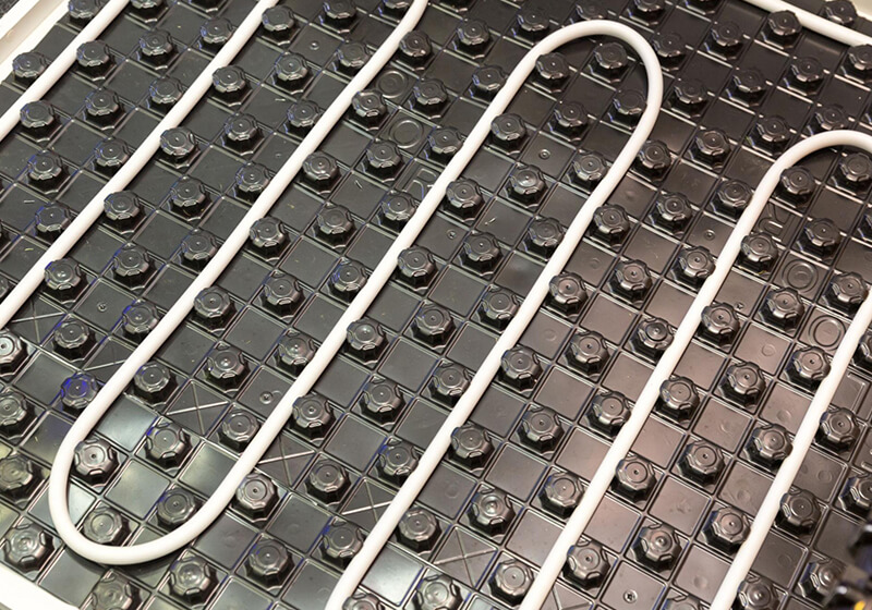
One of the most commonly used configurations is the serpentine layout, also known as the meander pattern. In this design, the pipe runs back and forth across the floor in parallel lines, forming a continuous path from the supply side to the return side. This layout is relatively simple to design and install, making it suitable for smaller or regularly shaped rooms where installation efficiency is a priority. However, due to the nature of the flow direction, heat is gradually lost along the pipe, which can result in a noticeable temperature gradient. Areas closer to the supply side tend to be warmer, while those near the return side may receive less heat, making this layout less ideal for spaces that require high levels of thermal comfort.
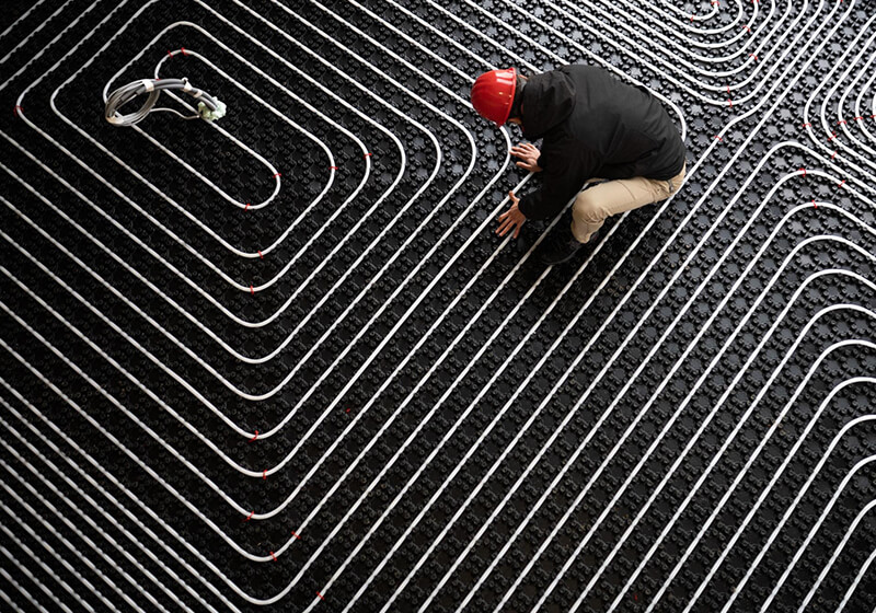
In contrast, the spiral layout, also referred to as the counterflow pattern, is widely regarded as a more balanced and efficient solution. In this configuration, supply and return pipes are arranged in parallel, allowing heat to be distributed more evenly across the floor surface. This significantly improves temperature uniformity and overall comfort, which is why spiral layouts are commonly preferred in residential applications such as living rooms and bedrooms. Although this layout requires more careful planning and slightly more complex routing, its thermal performance advantages often outweigh the added design effort. The flexibility of PE-RT pipes makes them particularly well-suited for this type of layout, as they can be bent smoothly to form continuous loops without introducing excessive stress or requiring additional fittings.
For larger or more complex spaces, hybrid layout strategies may be applied. These include double serpentine configurations or combinations of serpentine and spiral patterns, allowing designers to adapt to irregular floor plans, obstacles, or varying heat load conditions. Such approaches are often used in commercial projects or areas where heating demand is not evenly distributed. By combining different layout methods, it becomes possible to maintain acceptable heat distribution while accommodating practical installation constraints.
4. Pipe Spacing: How to Achieve Optimal Heat Output
Pipe spacing is one of the most critical factors in radiant floor heating design, as it directly influences heat output, temperature uniformity, and overall system efficiency. Proper spacing ensures that heat is distributed evenly across the floor surface while avoiding unnecessary energy consumption or localized overheating.
In general, pipe spacing refers to the distance between adjacent pipe runs, typically measured from center to center. The optimal spacing is determined by multiple factors, including heat demand, room function, insulation performance, and floor construction. As a result, spacing design should always be evaluated as part of the overall system planning rather than applied as a fixed value.
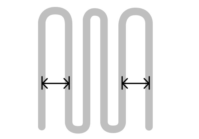
In typical residential radiant floor heating systems, pipe spacing commonly falls within the range of approximately 100 mm to 200 mm based on industry practices and design approaches aligned with standards such as EN 1264. Spacing around 100 mm is generally used in high heat demand areas, including bathrooms or perimeter zones with higher heat loss, while 150 mm is often applied in standard living spaces. Larger spacing, such as 200 mm, may be suitable for well-insulated areas with lower heating requirements. Smaller spacing increases the density of heat emission and improves temperature uniformity, but it also requires more pipe length and may increase installation costs. Conversely, wider spacing reduces material usage but may lead to uneven heating if not properly designed.
An important aspect of spacing design is the treatment of edge zones. Heat loss is typically higher near external walls, large windows, and doors, making these areas more challenging to heat effectively. To compensate, designers often reduce pipe spacing along the perimeter, a strategy commonly referred to as edge zone compensation. For example, spacing may be reduced from 150 mm to 100 mm in these zones to increase local heat output and maintain consistent indoor temperatures. This approach is particularly important in colder climates or in buildings with lower insulation performance.
Effective spacing design also requires balancing heat output with system efficiency. Applying tight spacing across the entire floor is not always necessary and may result in excessive energy use. Instead, spacing should be adjusted according to actual heat demand, while maintaining consistency within each loop and coordinating with loop length and system flow characteristics. A well-balanced design helps ensure efficient operation without overloading the heat source or increasing pumping requirements.
Material properties can further influence how easily a spacing design can be implemented. Due to its high flexibility, PE-RT pipe can be installed at tighter spacing with smooth bending and minimal mechanical stress. This allows for more precise layout adjustments, particularly in edge zones or complex floor plans. In addition, the ability to create continuous loops with fewer fittings supports stable flow and consistent heat distribution, contributing to overall system performance.
All technical data and recommended values mentioned in this article are for reference only. Actual design should comply with the latest applicable standards and be verified based on specific project requirements
5. Loop Length and Zoning Design
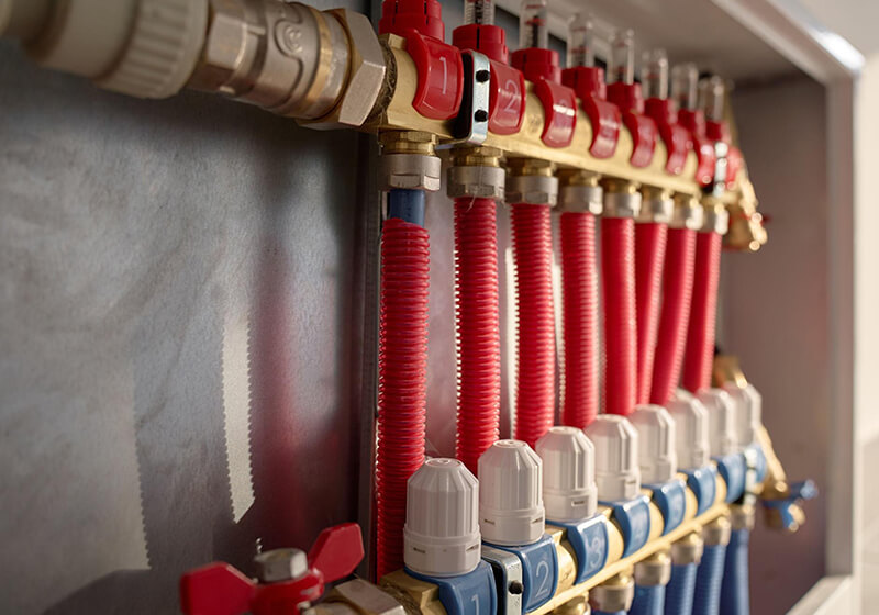
In radiant floor heating systems, loop length and zoning design play a critical role in ensuring consistent heat distribution, stable system operation, and efficient energy use. Even when pipe layout patterns and spacing are properly designed, poorly planned loops can still lead to flow imbalance, uneven heating, and reduced overall performance.
A key consideration in system design is maintaining an appropriate loop length. Each heating circuit must be designed within a recommended range to ensure effective water circulation and heat transfer. In most residential applications, loop lengths are typically controlled within approximately 80 to 120 meters, depending on factors such as pipe diameter, pump capacity, and overall system configuration. Actual loop length should be adjusted according to project conditions and confirmed by professional installers.
Loops that exceed this range may experience increased pressure loss and reduced flow rates, resulting in insufficient heat delivery at the far end of the circuit. Conversely, excessively short loops may lead to inefficient material usage and make system balancing more difficult. Maintaining relatively consistent loop lengths across the system is essential to ensure that each circuit receives a balanced flow of heated water, which directly impacts temperature uniformity.
Zoning design is another important aspect of radiant floor heating systems. By dividing the system into multiple zones, each area can be controlled independently based on its specific heating requirements. This is typically achieved through the use of a manifold, where multiple loops are connected and regulated. In practical applications, individual rooms or functional areas are often assigned separate loops or grouped circuits, allowing for more precise temperature control, improved energy efficiency, and better system responsiveness.
Closely related to zoning is the concept of hydraulic balance. A well-designed system must ensure that water flow is evenly distributed across all loops. Without proper balance, some areas may receive excessive heat while others remain underheated. Achieving this requires careful coordination between loop length, routing design, and manifold flow control. Systems should be designed to minimize large variations in loop length and avoid overly complex routing that may disrupt flow characteristics. Proper adjustment during installation and commissioning is also essential to ensure consistent long-term performance.
Material characteristics can further influence loop and zoning design. The flexibility of PE-RT pipes allows for smooth routing and continuous loop installation with minimal use of fittings, making it easier to maintain consistent loop lengths and adapt to different room layouts. This flexibility also simplifies manifold connections and reduces the risk of installation errors, contributing to a more reliable and efficient heating system overall.
6. Common Layout Mistakes to Avoid
We’ve analyzed failure data from HVAC forums (like Reddit HVAC) and MEP field reports. The most expensive radiant floor failures rarely happen because the pipe burst on its own; they happen due to layout negligence during installation.
Save or screenshot this matrix to ensure your next concrete pour doesn’t end in a liability claim:
| 🚨 Critical Layout Mistake | 💸 The Consequence (The Cost) | ✅ Field-Tested Solution (The Fix) |
|---|---|---|
| 1. Unequal Loop Lengths on One Manifold | Water takes the path of least resistance. A 100ft loop will overheat, while a 350ft loop on the same manifold stays freezing cold (Short-circuiting). | Keep all loops on a single manifold within 10% length variance. Never exceed 300 ft (90m) for a 1/2″ PE-RT loop. |
| 2. Skipping the 100 PSI Air Test During Pour | Laborers drop rebar or step on pipes. Concrete is poured over a punctured pipe. Result? A $10,000+ concrete slab tear-out. | Maintain 100 PSI of air pressure in the PE-RT pipes during the entire concrete pour. If the gauge drops, stop pouring immediately. |
| 3. Ignoring the EVOH Oxygen Barrier | Oxygen slowly permeates standard plastic pipes. It rusts cast-iron boilers, heat exchangers, and pumps from the inside out over 3-5 years. | Strictly source ISO 22391 / DIN 4726 compliant EVOH-coated PE-RT. Ensure the barrier is protected in a 3-layer or 5-layer co-extrusion. |
| 4. Crowding Toilet Flanges & Drains | When plumbers later drill into the slab to set toilets or fix drains, they pierce the PE-RT heating loop hidden in the concrete. | Maintain a strict 8 to 12-inch clearance zone away from all plumbing fixtures, floor drains, and future wall baseboards. |
| 5. Ignoring Perimeter Heat Loss | The center of the room is warm, but clients freeze when standing next to large exterior windows or glass doors. | Run the first supply (hottest water) along the exterior walls first, and tighten pipe spacing to 4-6 inches at the perimeter. |
Even with a solid understanding of layout principles and design strategies, mistakes can still occur during the planning or installation of radiant floor heating systems. These errors can lead to uneven heating, reduced efficiency, and long-term performance issues. By recognizing and avoiding the most common layout mistakes, designers and installers can significantly improve system reliability and overall comfort.
One of the most frequent issues in floor heating installations is uneven pipe spacing. Inconsistent distances between pipe runs can result in areas with insufficient heat where spacing is too wide, while overly tight spacing may cause localized overheating. To achieve balanced performance, spacing should remain consistent within each loop and only be adjusted when necessary, such as in edge zones where heat loss is higher. A clearly defined layout plan is essential to maintain this consistency during installation.
Another common mistake is excessive loop length. When loops exceed the recommended range, pressure loss increases and water flow decreases, which can reduce heat delivery at the far end of the circuit. This often leads to cold spots and overall system imbalance. Dividing larger areas into multiple loops is a more effective approach to ensure stable and efficient heating performance.
Ignoring edge zones is also a critical design oversight. Areas near external walls, windows, and doors experience greater heat loss, and failing to compensate for this in the layout can result in noticeable temperature differences within the space. Reducing pipe spacing in these perimeter zones helps deliver additional heat where it is most needed, improving overall comfort.
Poor loop planning and routing can further compromise system performance. Unstructured layouts may lead to unnecessary pipe crossings, sharp bends, or uneven floor coverage, all of which can create installation challenges and increase mechanical stress on the pipes. Establishing a clear and practical routing plan before installation is essential to avoid these issues.
Imbalanced loop design is another factor that can negatively affect system efficiency. When loop lengths vary significantly, it becomes difficult to maintain proper hydraulic balance, causing some areas to receive more heat than others. Designing loops with similar lengths and using manifold flow controls can help achieve a more even distribution of heat throughout the system.
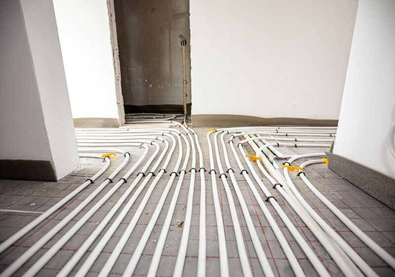
Finally, the excessive use of fittings within the floor should be avoided whenever possible. Additional joints increase the risk of leakage and reduce long-term system reliability. By using flexible materials such as PE-RT pipes, installers can create continuous loops with minimal connections, improving both safety and performance.
As a practical guideline, the layout design should always be finalized before installation begins and clearly marked on-site. A well-planned system not only enhances heating efficiency and comfort but also reduces installation time and minimizes the risk of errors.
7. Why MEP Contractors & Wholesalers Partner with Ctube for PE-RT Piping
Designing a mathematically perfect radiant floor layout is completely useless if the underlying pipe material degrades or fails under job-site stress.
What happens when you compromise on pipe quality?
If a procurement manager sources cheap, non-certified PE-RT without a proper EVOH barrier, the consequences are severe: oxygen permeates the system, rusting multi-thousand-dollar boilers within a few years. If the pipe is brittle in winter conditions, laborers force the bends, creating microscopic stress fractures. Once the concrete is poured, these micro-fissures become catastrophic under-slab leaks, leading to massive liability claims, structural damage, and a ruined contractor reputation.
At Ctube, we don’t just sell pipes; we engineer risk-mitigation solutions for HVAC contractors and wholesalers:
- Zero-Compromise EVOH Layers (DIN 4726): Our PE-RT pipes feature high-grade, multi-layer oxygen barriers. This protects expensive system components and completely shields your firm from future corrosion-related liability claims.
- Cold-Weather Flexibility (ISO 22391): Stop fighting rigid pipes on winter job sites. Ctube’s advanced molecular structure ensures the pipe remains highly flexible. This means faster installation of snail-pattern bends, zero kinking, and dramatically reduced labor hours.
- Custom Coil Sizing for Procurement ROI: Stop wasting money on off-cuts. We manufacture custom continuous roll lengths (e.g., 1,000 ft or more) tailored to your specific commercial project engineering specs, eliminating dangerous underground splices and optimizing your material ROI.
Don’t risk your next concrete pour on subpar materials. Contact Ctube for Wholesale Pricing & Technical Data Sheets
8. Conclusion
Designing an efficient radiant floor heating system requires more than simply selecting the right materials—it involves a comprehensive understanding of layout patterns, pipe spacing, loop length, and zoning strategies. Each of these elements plays a critical role in ensuring uniform heat distribution, stable system performance, and long-term energy efficiency.
By applying the principles and best practices outlined in this guide, designers, engineers, and installers can create floor heating systems that deliver consistent comfort, improved efficiency, and long-term reliability.
If you are planning a radiant floor heating project and looking for high-quality PE-RT pipe solutions, feel free to explore our product range or contact our team for technical support. Ctube is here to help you achieve the best possible results for your application.
9. FAQs
What is the maximum loop length for 1/2 inch PE-RT radiant pipe?
For standard commercial and residential heating, never exceed 300 feet (approx. 90 meters) per loop for 1/2" PE-RT pipe. Exceeding this causes critical pressure drops (head loss), which can burn out your circulator pump.
Does PE-RT pipe require an EVOH oxygen barrier for underfloor heating?
Yes. If your hydronic system includes any ferrous components (like cast iron pumps or boilers), using PE-RT with an EVOH barrier is mandatory to prevent oxygen permeation and subsequent internal corrosion.
What is the difference between Serpentine and Counter-flow layout patterns?
The Serpentine (snake) pattern creates uneven floor temperatures (hot at the start, cold at the end) and requires tight 180° bends. The Counter-flow (snail) pattern alternates hot and cold lines for uniform heating and uses sweeping 90° bends, which are easier to install.
How much pressure should be in the PE-RT pipes during a concrete pour?
Contractors should maintain a constant air or water pressure of at least 100 PSI in the PE-RT system before, during, and immediately after the concrete pour to detect any accidental punctures from rebar or laborers.
What is the typical BTU heat loss requirement for modern buildings?
Well-insulated modern buildings typically require 15–25 BTU/sq.ft, while average buildings need 25–35 BTU/sq.ft. High-load areas with large glass windows may require 35+ BTU/sq.ft, dictating tighter pipe spacing.
What is the ISO 22391 standard for PE-RT pipes?
ISO 22391 is the international standard specifying the material performance, hydrostatic strength, and dimensional tolerances for PE-RT (Polyethylene of Raised Temperature resistance) hot and cold water piping systems.
Why is the DIN 4726 standard critical for radiant floor heating?
DIN 4726 is the strict German standard that dictates the maximum allowable oxygen permeability for plastic piping in hydronic heating. Ctube PE-RT pipes strictly comply with this to guarantee boiler protection.
Are Ctube PE-RT pipes safe for drinking water (Potable use)?
Yes, non-barrier PE-RT pipes manufactured by Ctube are non-toxic, corrosion-resistant, and comply with international health and safety standards for potable water distribution.
How long is the service life of certified PE-RT pipes?
When manufactured to ISO 22391 standards and operated within designated temperature and pressure limits, PE-RT pipes have an expected service life of over 50 years integrated into the concrete slab.
Do multi-layer PE-RT pipes resist concrete chemical degradation?
Absolutely. High-quality PE-RT is inherently highly resistant to the alkaline environment of curing concrete, ensuring long-term structural integrity without degradation.
Can Ctube customize PE-RT coil lengths for large commercial MEP projects?
Yes. As a direct manufacturer, Ctube provides custom coil lengths (e.g., larger 1000+ ft continuous rolls) to match your specific engineering layouts, reducing scrap waste and eliminating underground joints.
Do you provide OEM/ODM services for PE-RT pipe wholesalers?
Yes, we offer comprehensive OEM and ODM manufacturing services, including custom pipe colors, specialized dimensions (SDR ratings), and custom brand printing on the pipe exterior for wholesalers.
How does Ctube ensure quality control before shipping PE-RT pipes?
Every batch undergoes rigorous in-house laboratory testing, including hydrostatic pressure tests, thermal stability checks, and oxygen permeability verifications to ensure 100% compliance with international standards before container loading.
What is the critical engineering difference between PE-RT Type I and Type II?
PE-RT Type I is designed for standard domestic or low-load residential applications (typically rated up to 60°C). PE-RT Type II utilizes an advanced molecular co-polymer structure designed for heavy-duty commercial hydronic applications, offering significantly higher hydrostatic design basis (HDB) strength and long-term hydrostatic stress resistance at 82°C to 95°C.
Can I use standard brass PEX crimp rings or PEX-A expansion tools on PE-RT pipes?
Yes, certified PE-RT pipes (complying with ASTM F2769) are fully compatible with standard PEX metal insert fittings utilizing copper crimp rings (ASTM F1807). However, cold-expansion tools (like ProPEX/Wirsbo ASTM F1960) should only be used if the PE-RT manufacturer specifically certifies that their pipe material formulation allows for mechanical expansion3. Always verify tool compatibility to prevent joint leaks.
How do you repair a punctured PE-RT pipe that is already embedded and cured in a concrete slab?
If a pipe is pierced after concrete is poured, you must locate the leak precisely using thermal imaging5. Chipping away a small pocket of concrete around the leak is required. Cut out the damaged section and connect a specialized, concrete-rated press/crimp coupling sleeve (ensure the coupling is wrapped in protective tape/membrane to prevent direct alkaline concrete contact). Never use compression fittings underground.
Can PE-RT pipes be used for radiant cooling systems, and what is the risk of "sweating"?
Yes, PE-RT is excellent for dual-use radiant heating and cooling systems. The risk of pipe condensation ("sweating") in the slab is managed by hydronic controls, not the pipe itself. MEP designs must include dew point sensors on the manifolds to ensure the chilled water supply temperature always remains 1–2°C above the ambient dew point of the room.
Does PE-RT have a lower thermal conductivity compared to copper or PEX?
PE-RT has a thermal conductivity of approximately 0.40 W/mK, which is virtually identical to PEX (around 0.38 - 0.41 W/mK). While vastly lower than copper, this moderate thermal conductivity is actually preferred in underfloor layouts because it allows for a controlled, slow, and uniform heat release into the thermal mass of the concrete slab rather than localized thermal shocks.



 English
  French
  Spanish
  German
  Arabic
  Indonesian
  Vietnamese