1. Introduction: Understanding Rigid Electrical Conduit
In the realm of electrical systems, conduits play a pivotal role in ensuring safety, longevity, and functionality.
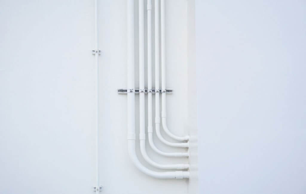
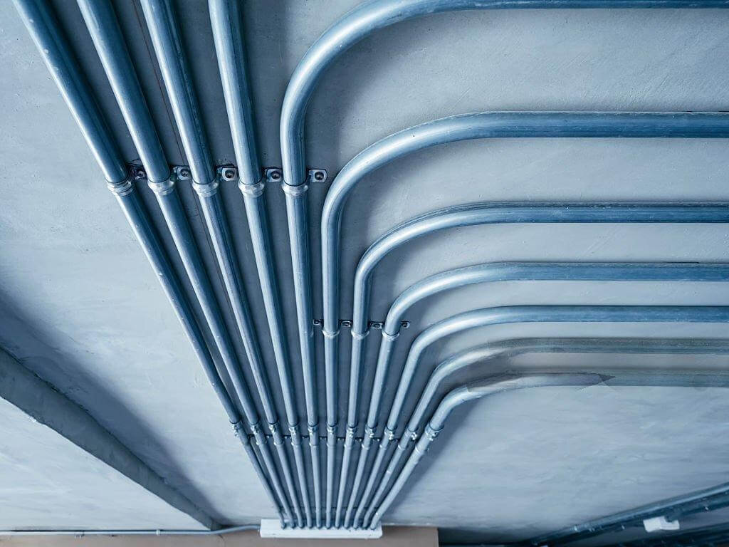
Electrical conduits serve as protective channels through which electrical wiring is run, shielding cables from physical damage, moisture, chemicals, and other environmental factors.
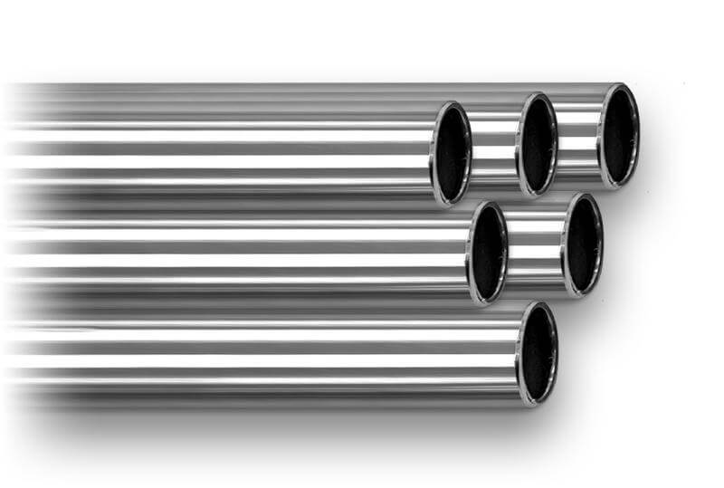
Among the various types of conduits available, rigid electrical conduit stands out for its robustness and suitability in both industrial and residential applications.
Rigid electrical conduit is available in a variety of forms, each designed to serve specific needs depending on the material and application.The primary materials used for rigid electrical conduits include PVC (Polyvinyl Chloride), galvanized steel, aluminum, and RTRC (Reinforced Thermosetting Resin Conduit), among others.Each material brings unique advantages, making rigid conduit versatile across a range of environments and project requirements.By the end of this post, you will have a thorough understanding of what rigid electrical conduit is, why it is an essential component in modern electrical systems, and how to incorporate it into your next project to maximize safety, efficiency, and compliance.
Metal Rigid Conduit includes types like Rigid Metal Conduit (RMC), Intermediate Metal Conduit (IMC), and Electrical Metallic Tubing (EMT), known for their strength and durability, making them suitable for industrial and outdoor use.Plastic Rigid Conduit, such as Rigid Polyvinyl Chloride (PVC), is lightweight, corrosion-resistant, and commonly used in environments where moisture protection is essential, like underground installations.
Additionally, RTRC conduit, made from fiberglass, offers excellent electrical insulation, thermal resistance, and corrosion protection, making it an ideal choice for applications requiring non-conductive and high-strength materials.
In the following article, we will present the details of rigid conduit made from different materials.
2. Types of Rigid Electrical Conduits – Detailed Introduction
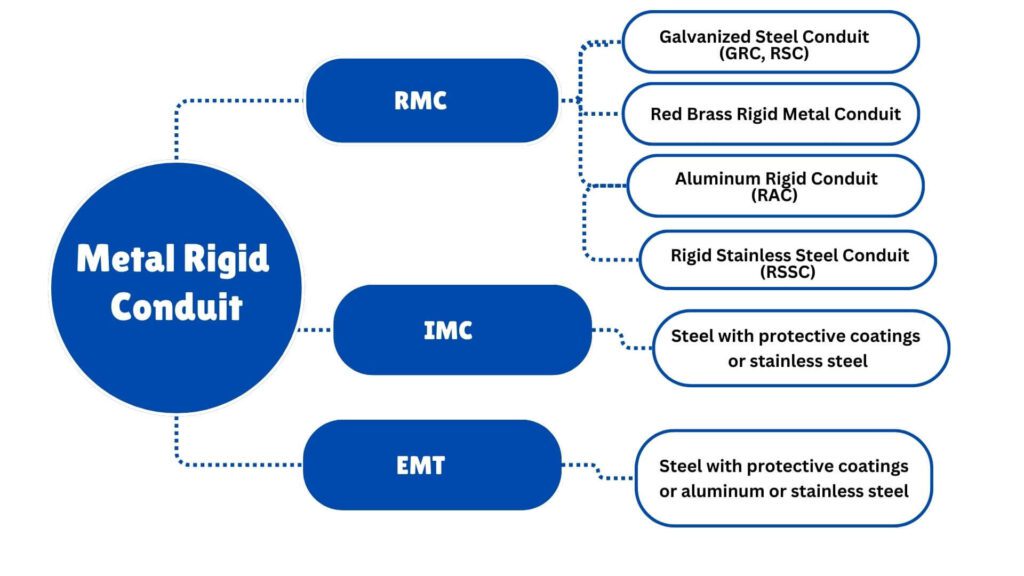
RMC is available in the following materials:
• Steel with protective coatings
• Aluminum
• Red brass
• Stainless steel
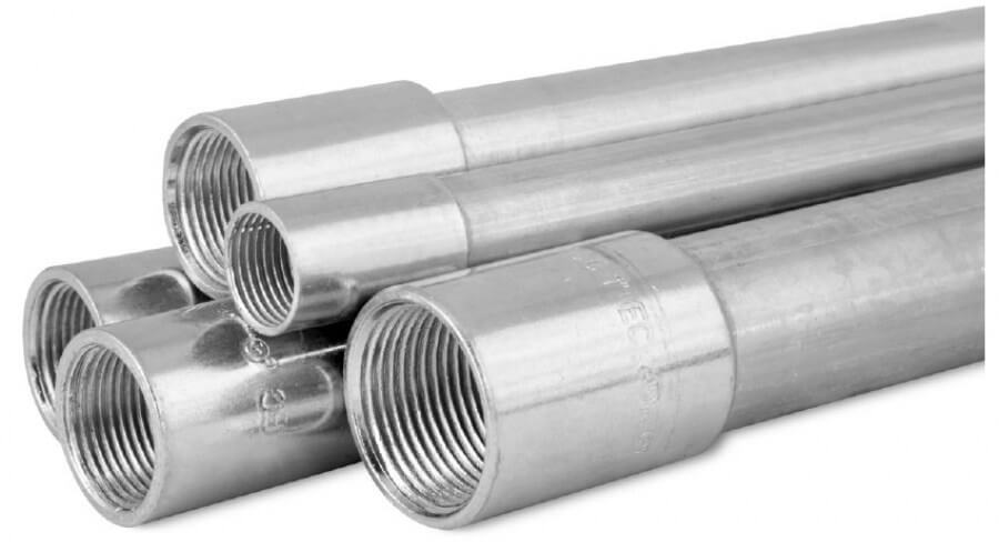
Material and Structure
Each tube used for Rigid Steel Conduit (RSC) shall be made of steel, ensuring that it is straight and features a circular cross-section.
| Metric Designator | Outside Diameter (mm) | Trade Size | Outside Diameter, a (in) |
|---|---|---|---|
| 12b | 17.15 | 3/8b | 0.675 |
| 16 | 21.34 | 1/2 | 0.840 |
| 21 | 26.67 | 3/4 | 1.050 |
| 27 | 33.40 | 1 | 1.315 |
| 35 | 42.16 | 1-1/4 | 1.660 |
| 41 | 48.26 | 1-1/2 | 1.900 |
| 53 | 60.33 | 2 | 2.375 |
| 63 | 73.03 | 2-1/2 | 2.875 |
| 78 | 88.90 | 3 | 3.500 |
| 91 | 101.60 | 3-1/2 | 4.000 |
| 103 | 114.30 | 4 | 4.500 |
| 129 | 141.30 | 5 | 5.563 |
| 155 | 168.28 | 6 | 6.625 |
a Tolerances: Trade Size 12–41 (3/8–1-1/2) ± 0.38 mm (±0.015 in). Trade Size 53–155 (2–6) ± 1%.
b In the United States, 12 (3/8) trade size is permitted for special applications. In Canada, 12 (3/8) trade size is not permitted according to the Canadian Electrical Code, Part I.
Welded Seams
The welding process for RMC tubes must meet strict criteria to ensure safety and functionality.
Welded seams should not have metal trimmings, sharp edges, or projections that could interfere with the internal wiring or the installation process.
A slight bead along the interior of the seam is permissible, as long as it is smooth and does not exceed 0.38 mm (0.015 in) in height for trade sizes 12 to 53 (3/8 inch to 2 inches) or 0.51 mm (0.020 in) for trade sizes 63 to 155 (2 ½ inches to 6 inches).
Standard Length and Weight Requirements
The standard length of straight zinc-coated conduit or bare threaded tubes to be coated with an alternate corrosion-resistant material, including one coupling, must follow the specifications detailed Table in the followinggs.
These tables outline the dimensions and weights for conduit that complies with the given standards.
| Metric Designator | Length of Straight Conduita (mm) |
Min. Acceptable Weight of 10 Lengths of Conduit with Ten Couplings, (kg) Finished Zinc Coated Conduitb |
Min. Acceptable Weight of 10 Lengths of Conduit with Ten Couplings, (kg) Bare Threaded Tubec |
Trade Size | Length of Straight Conduit Feet and Inchesa ±1/4 |
Min. Acceptable Weight of 10 Lengths of Conduit with Ten Couplings, (lbs) Finished Zinc Coated Conduitb |
Min. Acceptable Weight of 10 Lengths of Conduit with Ten Couplings, (lbs) Bare Threaded Tubec |
|---|---|---|---|---|---|---|---|
| 12d | 3035 | 23.4 | 22.6 | 3/8 | 9′–11 1/2″ | 51.5 | 48.6 |
| 16 | 3030 | 35.8 | 34.4 | 1/2 | 9′–11″ | 78.9 | 75.8 |
| 21 | 3030 | 47.6 | 45.5 | 3/4 | 9′–11″ | 104.9 | 100.3 |
| 27 | 3030 | 69.4 | 65.8 | 1 | 9′–11″ | 153.0 | 145.1 |
| 35 | 3025 | 91.2 | 87.8 | 1-1/4 | 9′–11″ | 201.0 | 193.5 |
| 41 | 3025 | 112.9 | 109.4 | 1-1/2 | 9′–11″ | 249.0 | 241.2 |
| 53 | 3035 | 150.4 | 144.3 | 2 | 9′–11 1/2″ | 331.6 | 318.1 |
| 63 | 3010 | 209.6 | 203.4 | 2-1/2 | 9′–10 1/4″ | 462.0 | 448.4 |
| 78 | 3010 | 239.0 | 233.4 | 3 | 9′–10 1/4″ | 527.0 | 514.8 |
| 91 | 3010 | 274.1 | 268.4 | 3-1/2 | 9′–10 1/4″ | 604.4 | 591.5 |
| 103 | 2995 | 312.0 | 305.3 | 4 | 9′–10″ | 687.6 | 672.9 |
| 129 | 2995 | 591.7 | 578.6 | 5 | 9′–10″ | 1304.9 | 1275.6 |
| 155 | 2995 | 797.1 | 781.4 | 6 | 9′–10″ | 1757.0 | 1722.7 |
a The lengths indicated are designed to produce a 3.05 m (10 ft) length of conduit when a straight-tapped conduit coupling is attached.
b This conduit is protected with a zinc or zinc-based coating consisting primarily of zinc.
c This conduit is intended to be protected with an alternate corrosion-resistant coating.
d In the United States, 12 (3/8) trade size is permitted for special applications. In Canada, 12 (3/8) trade size is not permitted according to the Canadian Electrical Code, Part I.
Test Requirements
Tubing Testing of Rigid Steel Conduit
The tube testing process involves bending a sample of the smallest available trade size into a quarter circle around a mandrel, first at room temperature and then after conditioning it at 0°C (32°F) for 60 minutes.
The tube must not crack or break its weld. If the tube has a nonmetallic coating and is rated for temperatures below 0°C, the test is performed at that lower temperature.
| Coatings | Tests | Clause # |
|---|---|---|
| Zinc | Bend Test Cold Bend Zinc Coating Test |
6.2.1.1 6.2.1.3 6.2.2 |
| Alternate Corrosion-Resistant | Bend Test Cold Bend Ultraviolet Light and Water Salt Spray (Fog) Moist CO₂–SO₂–Air Tensile Adhesion Flame Propagation |
6.2.1.1 6.2.1.3 6.2.4.3 6.2.4.5 6.2.4.6 6.2.4.8 6.2.4.9 6.2.4.11 |
| Alternate Corrosion-Resistant Nonmetallic (in addition to the above) | Assembly, Bending, Resistance, Pull, and Fault Current Electrical Continuity Identification of Compounds Cold Impact |
5.3.3.2 5.3.5.2 6.2.1.5 6.2.1.0 |
| Organic | Bend Test Cold Bend Identification of Compounds Elasticity Warm Humid Air Test |
6.2.1.1 6.2.1.3 6.2.1.5 6.2.3.5 6.2.3.2 |
| Supplementary Coatings | Detrimental Effects to Primary Coating Fit of Couplings Electrical Continuity Flame Propagation |
5.3.5.2 5.3.5.2 5.3.5.2 6.2.4.11 |
| Surface Treatment | N/A if less than 0.038 mm (0.00015 in) thickness | 5.3.6.1 |
Coating Testing of Rigid Steel Conduit
The table in the following outlines different tests for various types of coatings applied to tubes, including zinc, alternate corrosion-resistant, nonmetallic, organic, and supplementary coatings.
These tests assess the coating’s performance under different conditions such as bending, exposure to UV light, salt spray, cold temperatures, and electrical continuity.
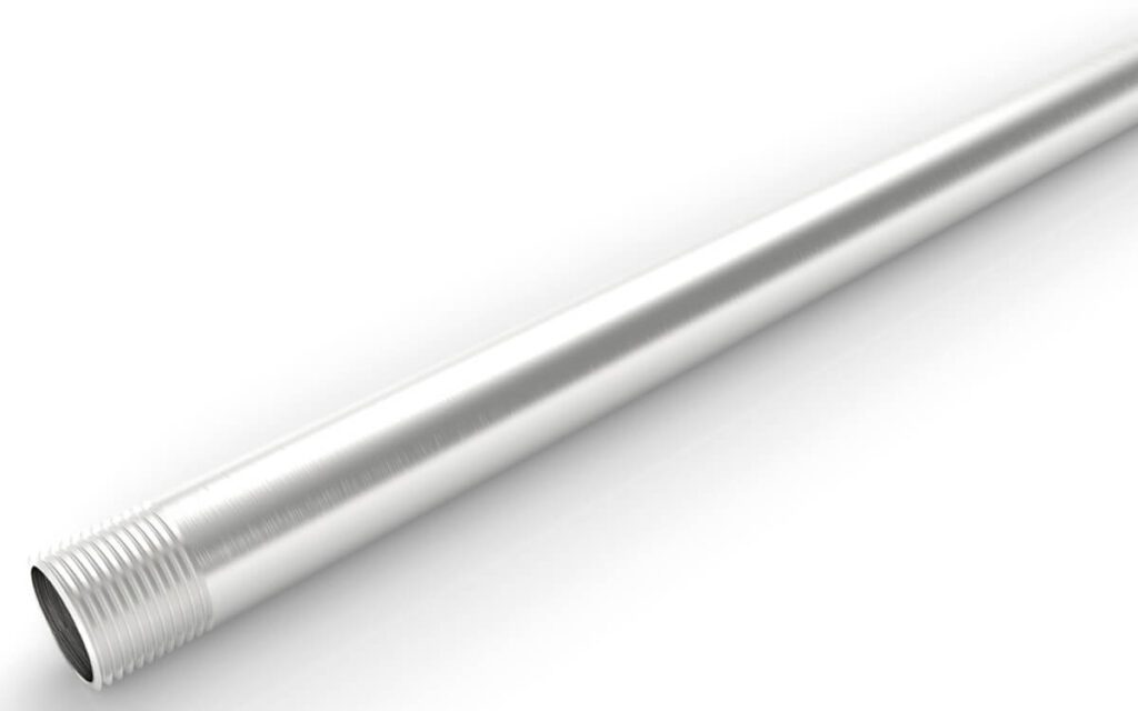
A threadable stainless steel raceway of circular cross-section designed for the physical protection and routing of wire conductors and use as an equipment grounding conductor when installed utilizing appropriate fittings.
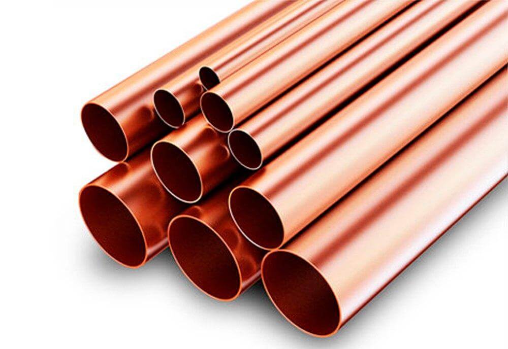
Electrical Rigid Metal Conduit – Red Brass (ERMC-RB)
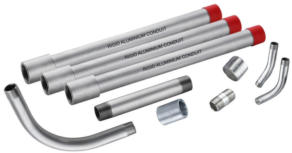
Electrical Rigid Metal Conduit – Aluminum (ERMC-A)
| Trade Size | Nominal Inside Diameter (in.) | Outside Diameter (in.) | Wall Thickness (in.) | Length w/o Coupling (ft & in.) | Min Weight (10 pcs with Couplings) (lb) |
|---|---|---|---|---|---|
| 1/2 | 0.632 | 0.840 | 0.104 | 9’11-1/4″ | 27.4 |
| 3/4 | 0.836 | 1.050 | 0.107 | 9’11-1/4″ | 36.4 |
| 1 | 1.063 | 1.315 | 0.126 | 9’11” | 50.7 |
| 1-1/4 | 1.394 | 1.660 | 0.138 | 9’11” | 66.2 |
| 1-1/2 | 1.624 | 1.900 | 0.138 | 9’11” | 86.2 |
| 2 | 2.067 | 2.375 | 0.154 | 9’10-1/2″ | 125.0 |
| 2-1/2 | 2.489 | 2.875 | 0.193 | 9’10-1/2″ | 182.5 |
| 3 | 3.068 | 3.500 | 0.225 | 9’10-1/4″ | 236.8 |
| 3-1/2 | 3.570 | 4.000 | 0.245 | 9’10-1/4″ | 358.7 |
| 4 | 4.032 | 4.500 | 0.265 | 9’10” | 454.9 |
| 5 | 5.073 | 5.563 | 0.245 | 9’10” | 454.9 |
| 6 | 6.093 | 6.625 | 0.266 | 9’10” | 604.4 |
| Trade Size | Outside Diameter (in.) Max |
Outside Diameter (in.) Min |
Wall Thickness (in.) Max |
Wall Thickness (in.) Min |
Nominal Inside Diameter (in.) | Length w/o Coupling (ft & in.) |
|---|---|---|---|---|---|---|
| 1/2 | 0.820 | 0.810 | 0.085 | 0.070 | 0.659 | 9’11-1/4″ |
| 3/4 | 1.034 | 1.024 | 0.090 | 0.075 | 0.863 | 9’11-1/4″ |
| 1 | 1.295 | 1.285 | 0.100 | 0.085 | 1.063 | 9’11” |
| 1-1/4 | 1.645 | 1.630 | 0.105 | 0.085 | 1.448 | 9’11” |
| 1-1/2 | 1.890 | 1.875 | 0.115 | 0.090 | 1.683 | 9’11” |
| 2 | 2.367 | 2.352 | 0.115 | 0.095 | 2.150 | 9’11” |
| 2-1/2 | 2.867 | 2.847 | 0.160 | 0.140 | 2.575 | 9’10-1/2″ |
| 3 | 3.486 | 3.466 | 0.160 | 0.140 | 3.176 | 9’10-1/2″ |
| 3-1/2 | 3.981 | 3.961 | 0.160 | 0.140 | 4.161 | 9’10-1/4″ |
| 4 | 4.476 | 4.456 | 0.160 | 0.140 | 4.166 | 9’10-1/4″ |
• Steel with protective coatings
• Aluminum
The interior surface shall be coated with either zinc or an organic coating. This interior coating must maintain a smooth, continuous surface, with minor variations due to uneven coating flow considered acceptable.
| Trade Size | Metric Designator | Maximum Length (ft) | Maximum Length (m) |
|---|---|---|---|
| 1/2 – 3/4 | 16 – 21 | 10′ 1/4″ | 3.05 |
| 1 – 2 | 27 – 53 | 15′ 1/4″ | 4.58 |
| 2-1/2 – 4 | 63 – 103 | 20′ 1/4″ | 6.10 |
Article 342 Intermediate Metal Conduit mentioned that IMC is available in the following materials:
- Steel with protective coatings
- Aluminum
| Trade Size | Metric Designator | External Diameter (in.) | Internal Diameter (in.) | Wall Thickness (in.) | Aluminum Min Weight (lb/ft) | Stainless Steel Min Weight (lb/ft) |
|---|---|---|---|---|---|---|
| 1/2 | 16 | 0.705 ±0.005 | 0.622 | 0.042 | 0.099 | 0.300 |
| 3/4 | 21 | 0.922 ±0.005 | 0.824 | 0.049 | 0.159 | 0.500 |
| 1 | 27 | 1.163 ±0.005 | 1.049 | 0.057 | 0.221 | 0.700 |
| 1-1/4 | 35 | 1.510 ±0.005 | 1.380 | 0.065 | 0.381 | 1.100 |
| 1-1/2 | 41 | 1.740 ±0.005 | 1.610 | 0.065 | 0.430 | 1.200 |
| 2 | 53 | 2.197 ±0.005 | 2.067 | 0.065 | 0.484 | 1.380 |
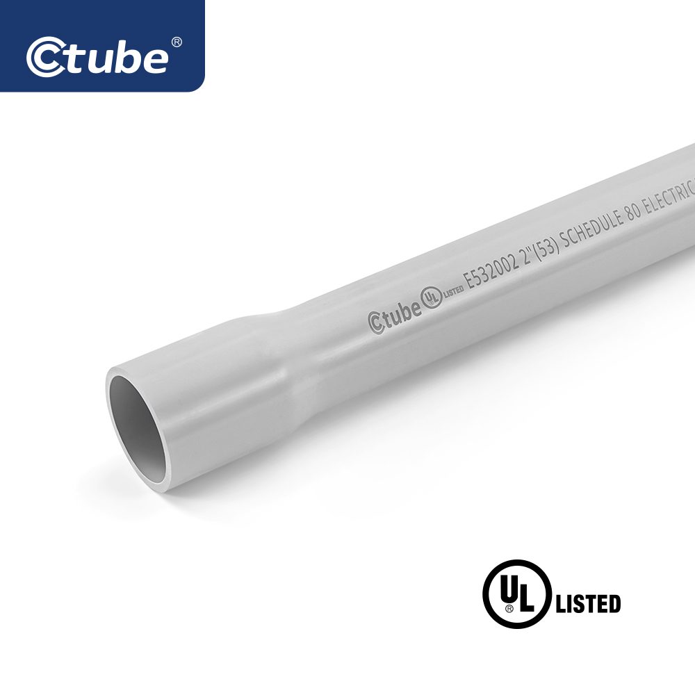
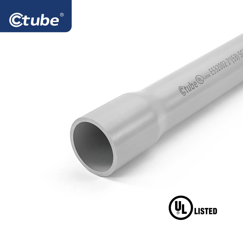
Test for Rigid PVC Conduit
Schedule 40 and Schedule 80 conduits have defined outside diameters and minimum wall thicknesses per trade size. These ensure structural integrity for various applications.
Conduit samples are tested using ASTM D 638. Aged samples must retain 95% of the tensile strength of unaged samples. Minimum strength is 5,000 psi for Schedule 40/80, and 4,000 psi for Type A and EB conduit.
Ten 6-inch conduit samples are tested using dropped weights. No more than three may crack or tear beyond 1/32 inch. Different weights are used: 20 lb for SCH 40, Type A, and EB; 75 lb for SCH 80.
Conduit must self-extinguish within 5 seconds after flame exposure and not ignite nearby materials. The test resembles the UL 94 V-0 rating, requiring high flame retardancy and no flaming drips.
Conduits must not deform or pull apart under pressure between steel plates. Flattened samples must maintain at least 70% of their original inside diameter.
Crush resistance measures a material’s ability to withstand steady, compressive forces (e.g., soil pressure). Impact resistance measures response to sudden shocks or drops. Both are critical in different field conditions.
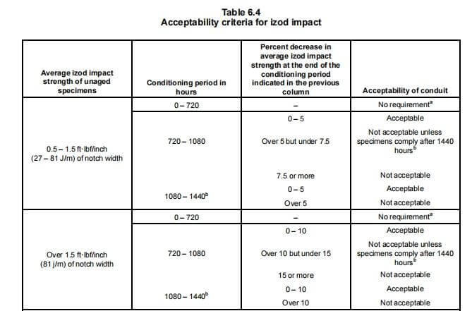
For Schedule 40 and 80, sunlight exposure testing involves Izod impact strength (≥0.5 ft-lbf/inch). Specimens are tested over periods of 720–1440 hours following ASTM D 256 methods to ensure durability in UV conditions.
Types are defined by diameter system and wall thickness:
- ID: Inside Diameter
- IPS: Iron Pipe Size (Outside Diameter)
- Wall Thickness: SW (Standard), MW (Medium), HW (Heavy), XW (Extra Heavy)

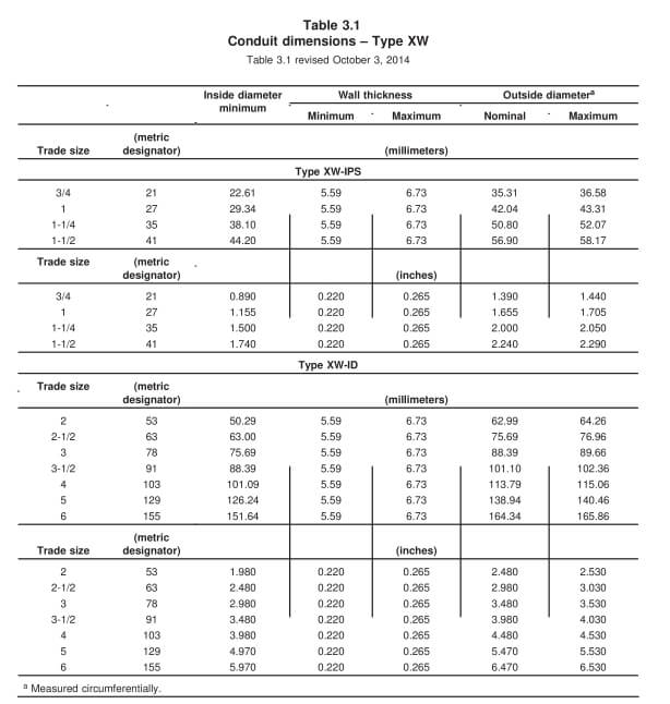
Applications:
- Aboveground: UL 2515
- Underground: UL 2420
Each specimen is tested for post-flame duration: flaming should not exceed 30 seconds after the first four flame applications, nor 60 seconds after the fifth.
The optional FT4 flame test is one of the most rigorous, required in certain Canadian noncombustible building constructions. It involves exposure to a 70,000 BTU/hour flame for 20 minutes.
Pass criteria: Charred length must not exceed 1.5 m (5 ft.) from the bottom of the burner (CSA C22.2 No.38).
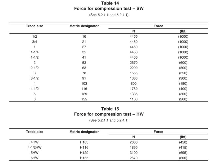
Qualification Tests for Reinforced Thermosetting Resin Conduit (RTRC)
3. Exploring Burial Depth Requirements for Rigid Electrical Conduits
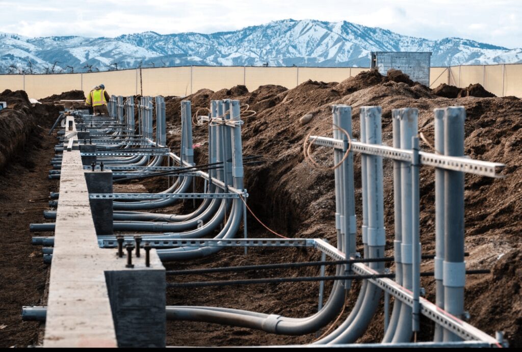
In the realm of electrical installations, the proper burial depth of conduits is paramount for ensuring safety, compliance, and durability. Rigid electrical conduits, including rigid metal conduit (RMC), nonmetallic conduits like PVC, and fiberglass conduits, have specific burial depth requirements dictated by both the National Electrical Code (NEC) and local building codes.
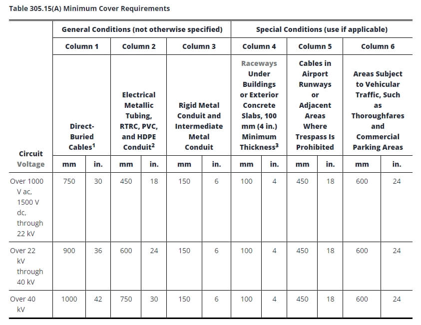
Notes:
1. Cover shall be defined as the shortest distance in millimeters (inches) measured between a point on the top surface of any direct-buried conductor, cable, conduit, or other raceway and the top surface of finished grade, concrete, or similar cover.
2. Lesser depths shall be permitted where cables and conductors rise for terminations or splices or where access is otherwise required.
3. Where solid rock prevents compliance with the cover depths specified in this table, the wiring shall be installed in a metal or nonmetallic raceway permitted for direct burial. The raceways shall be covered by a minimum of 50 mm (2 in.) of concrete extending down to rock.
4. In industrial establishments, where conditions of maintenance and supervision ensure that qualified persons will service the installation, the minimum cover requirements for other than rigid metal conduit and intermediate metal conduit shall be permitted to be reduced 150 mm (6 in.) for each 50 mm (2 in.) of concrete or equivalent placed entirely within the trench over the underground installation.
5. Direct Buried Cables: Underground direct-buried cables that are not encased or protected by concrete and are buried 750 mm (30 in.) or more below grade shall have their location identified by a warning ribbon that is placed in the trench at least 300 mm (12 in.) above the cables.
6. Electrical Metallic Tubing, RTRC, PVC, and HDPE Conduit: These may be listed by a qualified testing agency as suitable for direct burial without encasement. All other nonmetallic systems shall require 50 mm (2 in.) of concrete or equivalent above the conduit in addition to the table depth.
7. Raceways Under Buildings or Exterior Concrete Slabs (100 mm / 4 in. Minimum Thickness): The slab shall extend a minimum of 150 mm (6 in.) beyond the underground installation, and a warning ribbon or other effective means suitable for the conditions shall be placed above the underground installation.
8. Other nonshielded cables not covered in 305.15(A)(1) or (A)(2) shall be installed in rigid metal conduit, intermediate metal conduit, or rigid nonmetallic conduit encased in not less than 75 mm (3 in.) of concrete.
9. Conductors Emerging from the Ground: These shall be enclosed in listed raceways. Raceways installed on poles shall be of rigid metal conduit, intermediate metal conduit, RTRC-XW, Schedule 80 PVC conduit, or equivalent, extending from the minimum cover depth specified in Table 305.15(A) to a point 2.5 m (8 ft) above finished grade.
Environmental factors significantly influence conduit burial depth. Soil conditions, such as stability and moisture content, can dictate how deeply a conduit should be installed to ensure it remains secure over time. For instance, in rocky or unstable soils, deeper burial may be necessary to prevent damage from soil movement.
Traffic loads also play a critical role, particularly in areas where conduits are installed beneath roads or parking lots. Here, deeper burial is often required to protect the conduits from the weight and vibration of vehicles and heavy equipment.
4. Installation Guidelines for Different Types of Rigid Conduit
Before starting, gather the following tools and materials:
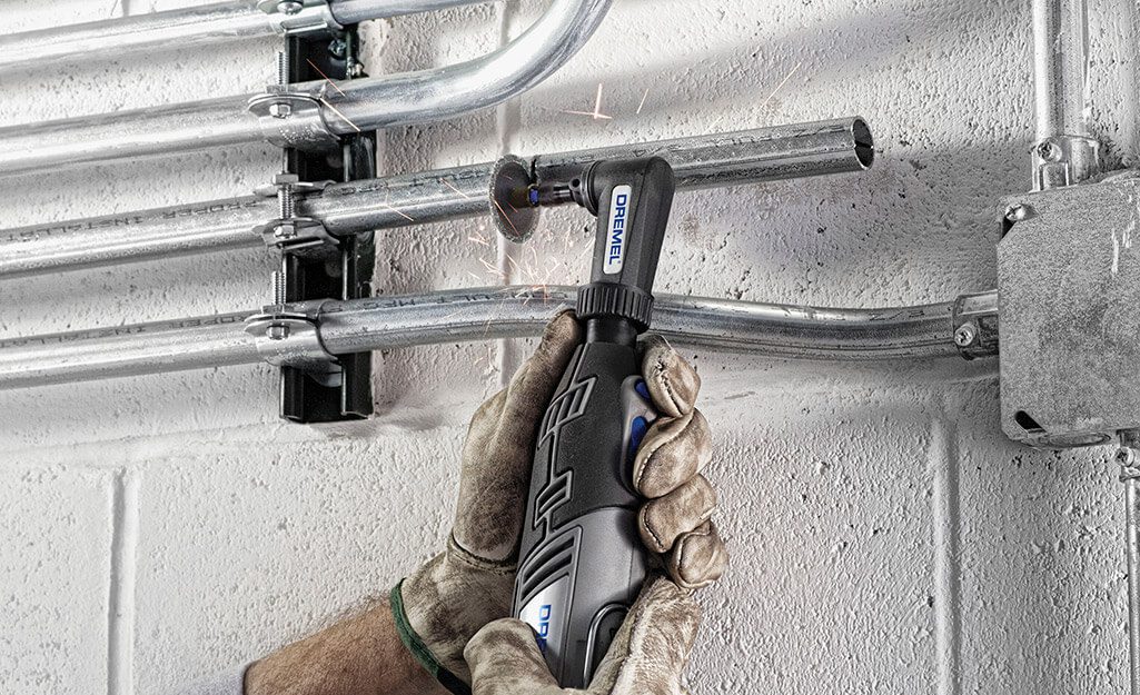
• Cutting tools: Hacksaw or roll cutter (if cutting is required).
• Reamer: To remove burrs inside the conduit after cutting.
• Conduit bender: For making precise bends.
• Wrenches: Appropriately sized.
• Thread-sealing compound or corrosion-resistant paint: To protect threads if necessary.
Also confirm you have all necessary fittings, couplings, and connectors to ensure proper grounding.
• Measure and Cut: Measure required length and cut cleanly with a saw.
• Ream: Remove burrs inside the conduit to avoid wire damage.
• Threading: Use a standard ¾-inch per foot (NPT) die for threading if needed. Threads should be smooth and clean.
For pre-threaded conduit, skip threading but protect exposed or damaged threads.
• Hand-Tighten and Wrench Finish: Start hand-tightening, then wrench-tighten typically one full turn beyond hand-tight.
• Avoid Over-Tightening: Excessive force can damage threads and coating. Do not use wrench extensions.
• For threadless fittings, push conduit fully into fitting and secure with appropriate torque.
• Hand Bending: Small sizes (½ to 1 inch) can be bent with a hand bender; larger sizes require mechanical or power benders.
• Precision: Mark bends; avoid exceeding 90° between pulling points.
• Avoid Kinks: Prevent flattening or kinking, which reduces space and complicates wire pulling.
• For pre-threaded conduit, avoid damaging threads during bending.
• Use straps, hangers, or clamps to secure conduits to walls, ceilings, or structural members.
• For vertical runs, secure conduit at the top end to prevent sagging.
• For conduits transitioning from concrete to soil or underground, apply approved coatings, wraps, or PVC-coated conduit for extra protection.
• Inspect factory-applied coatings for damage during installation.
• Apply corrosion-resistant compounds, zinc-rich paint, or corrosion-resistant tape as needed.
• Protect field-cut threads with corrosion-resistant, electrically conductive coatings.
• Perform continuity testing to confirm electrical continuity and grounding.
• Inspect all conduit connections for tightness and secure supports.
• Verify protective coatings remain intact and additional protections are applied as necessary.
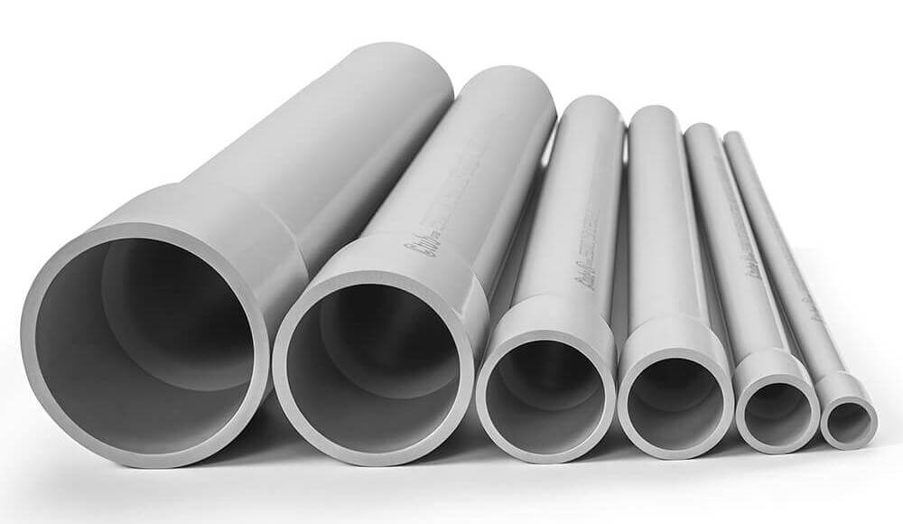
Before you begin, gather the necessary tools and materials for a successful PVC conduit installation:
PVC Conduit: The appropriate diameter and length for your project.
PVC Fittings: Couplings, elbows, junction boxes, and other components.
PVC Cement and Primer: To secure joints and fittings.
Conduit Cutter or Hacksaw: To cut the conduit to the required length.
Deburring Tool: To smooth the cut edges of the conduit.
Tape Measure: For accurate measurements.
Level: To ensure proper alignment.
Pull String or Fish Tape: To pull wires through the conduit after installation.
Before starting the installation, carefully plan the route for your PVC conduit. This includes measuring the distance between points where the conduit will run and mapping out where bends, fittings, and junctions will be needed.
Measure and Mark: Use a tape measure to determine the length of PVC conduit required for each section and mark where cuts will be made.
Account for Expansion and Contraction: PVC conduit expands and contracts with temperature changes, so you’ll need to leave some room for movement or install expansion fittings in long runs.
Cutting PVC conduit is much easier than cutting metal conduit, but it’s still important to make clean, precise cuts to ensure a smooth installation.
Cut the Conduit: Use a PVC conduit cutter or a fine-toothed hacksaw to cut the conduit to the measured lengths. Make sure the cuts are straight and clean.
Deburr the Edges: After cutting, use a deburring tool or a utility knife to remove any rough edges or burrs from inside and outside the conduit. This step is crucial to prevent damaging the wires when they’re pulled through the conduit.
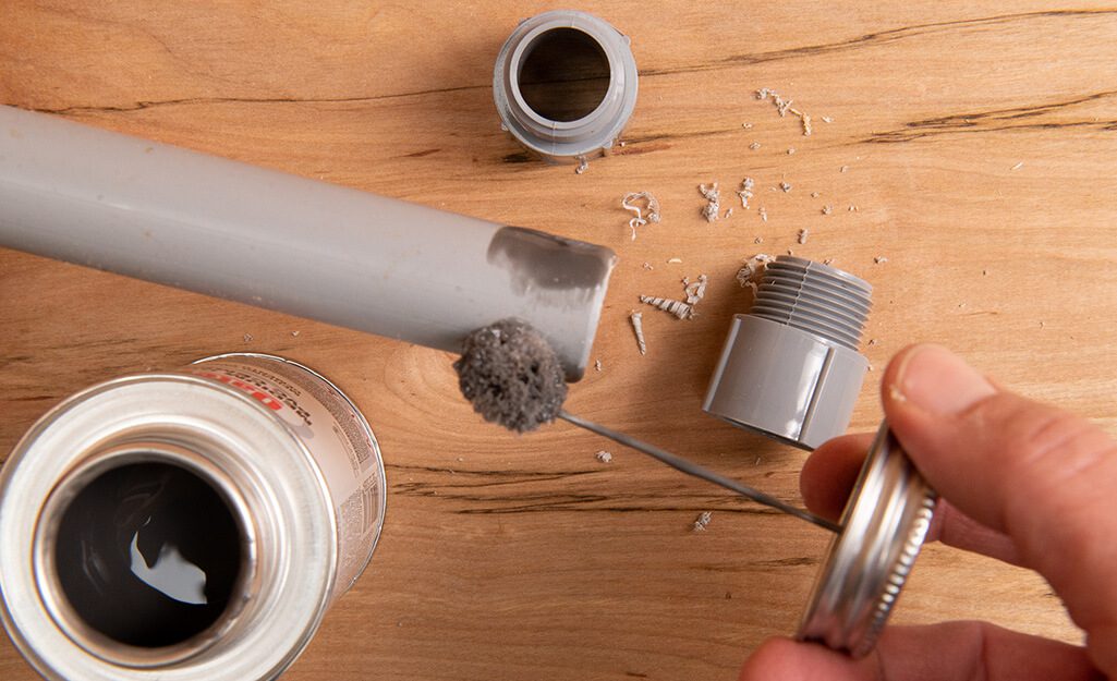
Unlike metal conduit, where threads or set-screw fittings are used, PVC conduit sections are joined by a process called solvent-welding. This involves using a primer and PVC cement to bond the conduit and fittings together.
Apply Primer: First, clean the ends of the conduit and the inside of the fittings using a PVC primer. The primer softens the material and prepares it for the bonding process.
Apply PVC Cement: Immediately after applying the primer, coat the same areas with PVC cement. Be sure to work quickly, as the cement dries fast.
Join the Conduit and Fittings: Push the conduit into the fitting, twisting slightly to ensure the cement spreads evenly. Hold the pieces together for a few seconds to ensure a strong bond.
Wipe Off Excess Cement: Remove any excess cement that squeezes out during the connection process. Allow the joint to set according to the manufacturer’s instructions before handling it further.
This solvent-welding process creates a watertight seal, making PVC ideal for outdoor and underground installations where moisture resistance is critical.
Bending PVC conduit is different from bending metal conduit. PVC can be bent using heat to create smooth, custom bends without the need for prefabricated elbows in some situations.
Heat the PVC Conduit: Use a heat gun or PVC bending heater to warm the section of the conduit where the bend is needed. Be sure to apply heat evenly to avoid deforming the conduit.
Make the Bend: Once the conduit is pliable, bend it slowly to the desired angle. Hold it in place until the conduit cools and retains the shape.
Use Pre-Made Elbows: For most installations, it’s easier to use factory-made 90-degree or 45-degree PVC elbows, which are glued in place using the same solvent-welding process.
Since PVC is more flexible and lightweight than metal conduit, it requires proper support to prevent sagging or movement over time.
Install Conduit Straps or Clamps: Support the PVC conduit at regular intervals by securing it with conduit straps or clamps. Follow NEC guidelines, which recommend supporting PVC every 3 to 6 feet, depending on the diameter of the conduit.
Allow for Expansion: PVC conduit expands and contracts with temperature changes. In longer runs, install expansion fittings to allow movement without stressing the joints. Expansion fittings are crucial for outdoor or sun-exposed installations where temperature fluctuations are significant.
After the conduit is installed and the cement joints have cured, you can pull wires through the conduit.
Use a Fish Tape or Pull String: Feed the fish tape or pull string through the conduit run, then attach the wires securely to the tape.
Pull the Wires: Slowly pull the wires through the conduit, ensuring that they don’t snag or get damaged on any rough edges.
Lubricate If Necessary: If the conduit run is long or has several bends, use a wire-pulling lubricant to reduce friction and make the wire-pulling process easier.
Once the wires are pulled and the system is set up, perform a final inspection to ensure everything is installed correctly and securely.
Check Connections: Ensure all solvent-welded joints are solid and that no fittings have loosened.
Verify Supports: Confirm that all conduit straps and clamps are properly spaced and secure.
For a successful RTRC conduit installation, gather the following tools and materials:
- RTRC Conduit: Appropriate diameter and lengths of conduit.
- RTRC Fittings: Couplings, elbows, and other necessary components.
- Two-Part Epoxy or Adhesive: To bond conduit sections and fittings.
- Hacksaw or Fine-Toothed Saw: For cutting the conduit to size.
- Deburring Tool or Sandpaper: To smooth cut edges.
- Measuring Tape and Level: For precise measurements and alignment.
- Pull String or Fish Tape: To pull wires through the conduit after installation.
- Heat Gun: For heat-shrink components if needed.
As with any conduit system, start by planning the route and layout for the RTRC installation. Identify the points where conduit runs will change direction, where fittings will be needed, and where access points or junction boxes should be placed.
Measure and Mark: Use a tape measure to accurately determine the lengths of conduit required and mark where cuts will need to be made.
Cutting RTRC conduit is similar to cutting PVC, but the material’s composition requires careful handling to prevent fiber damage.
Cut the Conduit: Use a hacksaw, reciprocating saw, or any fine-toothed saw to cut the conduit to the desired length. Make sure the cut is straight to allow for proper joining.
Deburr the Edges: After cutting, smooth the inside and outside edges using a deburring tool or sandpaper. This prevents damage to wire insulation.
Dust Control: When cutting RTRC, use PPE such as gloves, eye protection, and a dust mask or respirator to manage fiberglass dust.
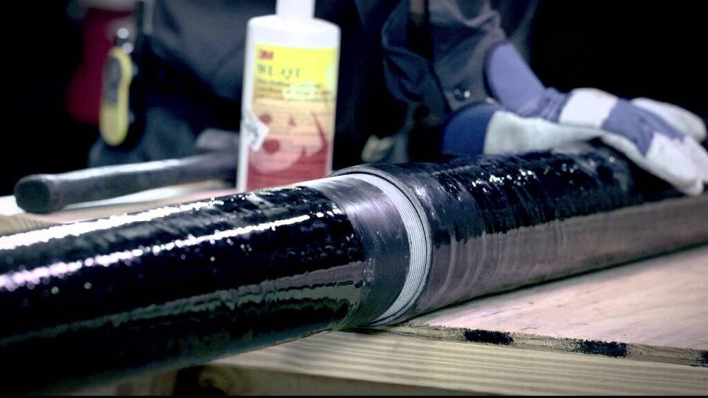
RTRC conduit is joined using adhesives or a two-part epoxy designed for fiberglass conduit systems.
Prepare the Surfaces: Clean conduit ends and fitting interiors to remove dust, dirt, and oil.
Apply the Adhesive: Use the recommended epoxy. Apply generously to both joining surfaces.
Join and Set: Insert and twist the conduit into the fitting. Hold briefly until set begins.
Curing Time: Allow full curing as per manufacturer guidelines before applying load or stress.
RTRC conduit needs adequate support, especially in horizontal applications:
- Use approved straps, hangers, or clamps every 6–10 feet per NEC requirements.
- Expansion Joints: Include expansion fittings in long runs or areas with temperature swings.
Bending RTRC conduit is typically not done on site:
- Use factory-made elbows and bends (e.g., 90°, 45°), joined with adhesive.
- No Heat Bending: Heating damages RTRC’s structural integrity.
Once adhesive is cured, proceed to wire installation:
- Use fish tape or pull string to guide wires through conduit.
- Apply lubricant on long or complex runs to ease pulling.
- Ensure NEC-compliant grounding and bonding, as RTRC is non-conductive.
Before energizing the system:
- Inspect all adhesive joints to confirm secure bonding.
- Verify that all supports are in place and at correct intervals.
5. Conclusion
| Features | RMC | IMC | EMT | PVC | RTRC |
|---|---|---|---|---|---|
| Cost | Highest initial cost | Moderate cost | Lower than RMC and IMC | Lowest initial cost | Moderate to high cost |
| Durability | Very durable, heavy-duty | Durable, but lighter than RMC | Less durable than RMC and IMC | Durable, but not as strong as metal | Very durable, resistant to impact |
| Corrosion Resistance | Good with coatings | Better with coatings | Prone to corrosion unless coated | Excellent, naturally resistant | Excellent, highly resistant |
| Installation Ease | Heavy, requires more labor | Moderate, lighter than RMC | Easiest to install | Easy, lightweight, and flexible | Easy to install, lightweight |
Importance of Selecting the Right Conduit for Different Environments
For above-ground applications, prioritize options with UV resistance to withstand harsh sunlight, while for underground installations, focus on moisture and corrosion resistance to protect against environmental factors.
Moisture-Prone Areas
In environments where moisture is prevalent—such as basements, bathrooms, or outdoor installations—choosing conduits with water resistance is vital.
Options like PVC or specialized moisture-resistant conduits help prevent corrosion, which can lead to electrical failures and safety hazards.
Additionally, moisture-resistant conduits often meet specific codes for wet locations, ensuring compliance with electrical standards.
Corrosion Risks
In industrial or commercial settings, conduits may be exposed to various chemicals, including solvents, acids, or caustics.
Using conduits made from materials that resist chemical degradation—such as certain types of PVC or metal conduits—helps maintain the integrity of the wiring.
This selection not only prevents damage to the conduit itself but also safeguards the surrounding environment and personnel from hazardous exposure.
In coastal areas or places with high humidity, selecting corrosion-resistant conduits is essential.
Options like fiberglass or stainless steel conduits can withstand harsh environmental conditions, preventing premature deterioration and ensuring long-term reliability.
This choice is particularly important for underground or submerged installations, where exposure to moisture and salts is unavoidable.
Extreme Temperatures
Regions that experience extreme temperatures, whether hot or cold, require conduits designed to withstand such conditions.
For instance, conduits that are rated for high heat or freeze resistance ensure that the wiring remains functional without compromising safety.
In extreme cold, flexible conduits may be necessary to prevent cracking, while in high heat, UV-resistant materials can protect against sun exposure.
By carefully considering these factors, you can make an informed choice that meets both performance needs and regulatory standards, ultimately contributing to the success of your project.
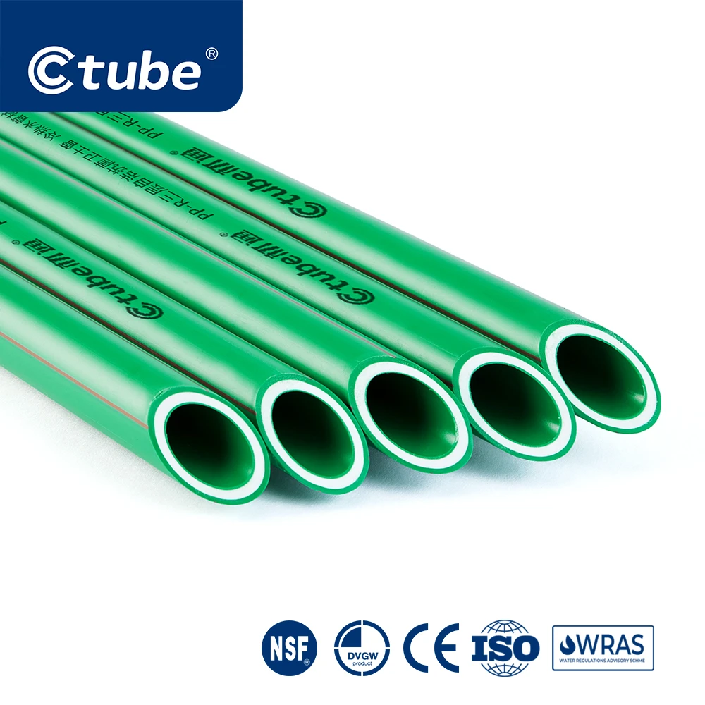
Ctube is a premier manufacturer of high-quality PVC conduit solutions, dedicated to delivering reliable and durable products for electrical installations.
Based in China, we specialize in producing a wide range of conduits designed to meet the diverse needs of various industries, all while ensuring compliance with international standards.
Our PVC rigid conduit adheres to rigorous certifications such as UL 651, AS/NZS 2053, and CSA, guaranteeing exceptional performance, durability, and safety across different regions.
Thank you for reading! We hope this post was helpful to your project. Wishing you success in all your work — and feel free to reach out to us if you have any project needs or inquiries.
FAQs
How does rigid conduit compare to flexible conduit?
Rigid conduit offers more protection due to its solid structure, making it ideal for environments with heavy mechanical stress or exposure to moisture and chemicals.
Flexible conduit is easier to install and allows for movement, making it more suitable for areas where flexibility is needed.
How is rigid conduit secured during installation?
Rigid conduit is secured using various types of fasteners, such as clamps, brackets, and straps, depending on the installation environment (indoor, outdoor, or underground). These fasteners ensure that the conduit remains firmly in place and protects the wiring inside.
How to turn a corner with rigid electrical conduit?
Conduit fittings play a crucial role in ensuring smooth turns for rigid conduit systems. Common fittings include elbows and sweep bends, designed to create 90-degree or angled turns such as 45-degree and 22.5-degree angles. Tee connectors are also frequently used to allow conduit to branch off into different directions.
Among rigid conduits, EMT (Electrical Metallic Tubing) is the easiest to bend. Tools like a conduit spring or conduit bender are essential for making precise bends, ensuring proper alignment and installation.